
Biomedical electrochemical sensor array and method of fabrication

a biochemical and sensor array technology, applied in the direction of instruments, non-metallic protective coating applications, material electrochemical variables, etc., can solve the problems of incompatibility of flexible materials with thin film processing techniques, inability to achieve fine line resolution for small or miniaturized electrodes, and limited well depth and/or precise boundary or perimeter definition during formation

Inactive Publication Date: 2005-10-27
ROCHE DIABETES CARE INC
View PDF99 Cites 141 Cited by
  • Summary
  • Abstract
  • Description
  • Claims
  • Application Information

AI Technical Summary

Benefits of technology

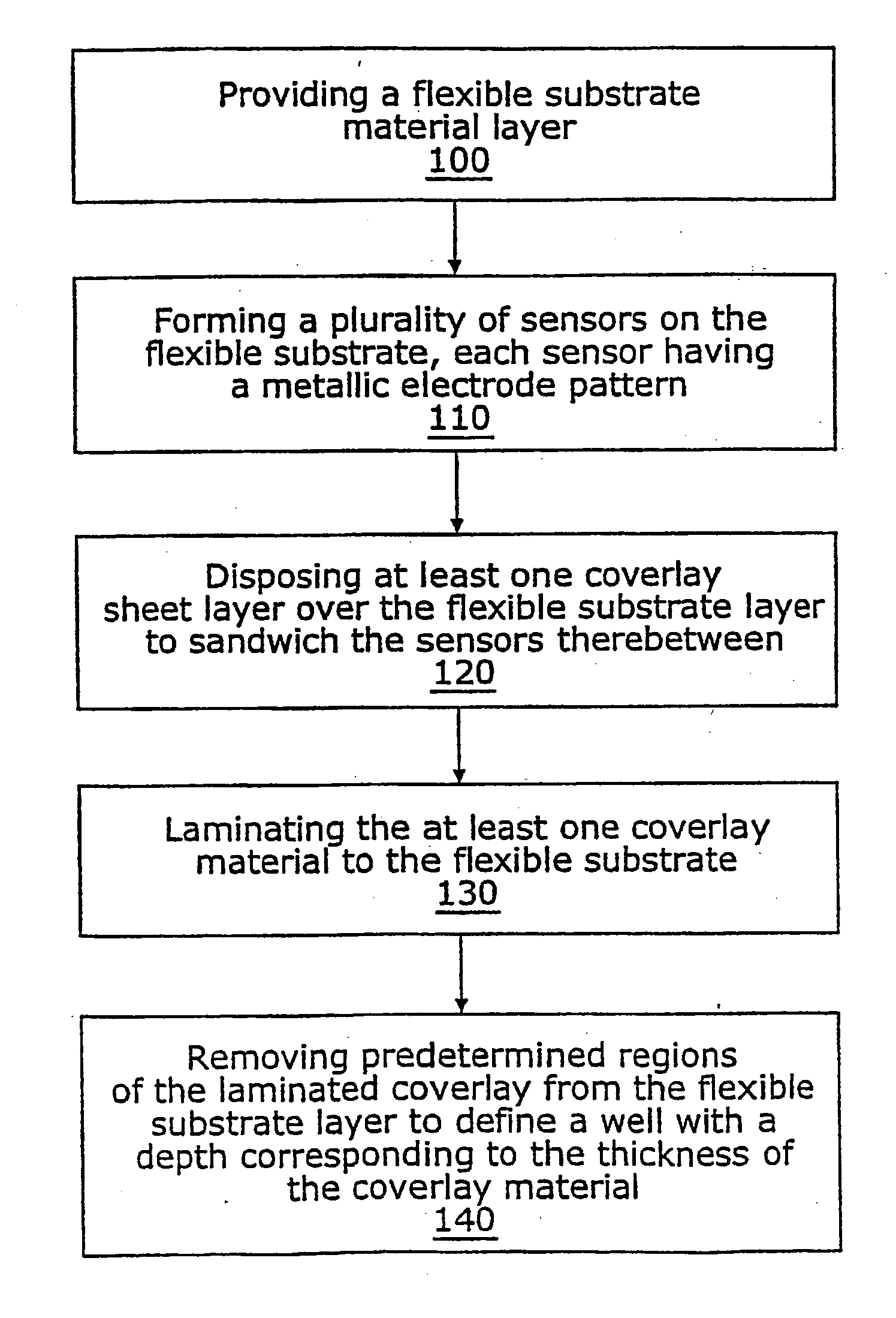
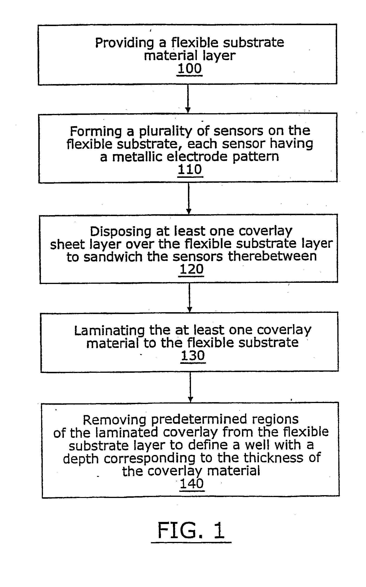
[0007] In certain embodiments, the present invention is directed to methods for fabricating a plurality of sensors on a flexible substrate, each sensor having at least one associated electrode and at least one well. As used herein, the term “well” means a reservoir or chamber used to receive or hold a quantity of fluid therein (typically sized and configured as a microfluidic

Problems solved by technology

In the past, thin film processing techniques have had problems generating coatings thick enough for proper well formation in chemical sensor applications.
In addition, screen printed materials used with thick film processing techniques may be either incompatible with flexible materials or inhibit the formation of fine line resolution desired for small or miniaturized electrodes.
Unfortunately, spin-coating methods can, as a practical matter, limit the well depth and / or precise boundary or perimeter definition during formation.
In addition, spin-coating methods may be limited to batch fabrication processes and are generally not commercially compatible with high volume, low-cost (continuous or semi-continuous) mass production methods.

Method used


Image

  • Biomedical electrochemical sensor array and method of fabrication
  • Biomedical electrochemical sensor array and method of fabrication
  • Biomedical electrochemical sensor array and method of fabrication

Examples


examples

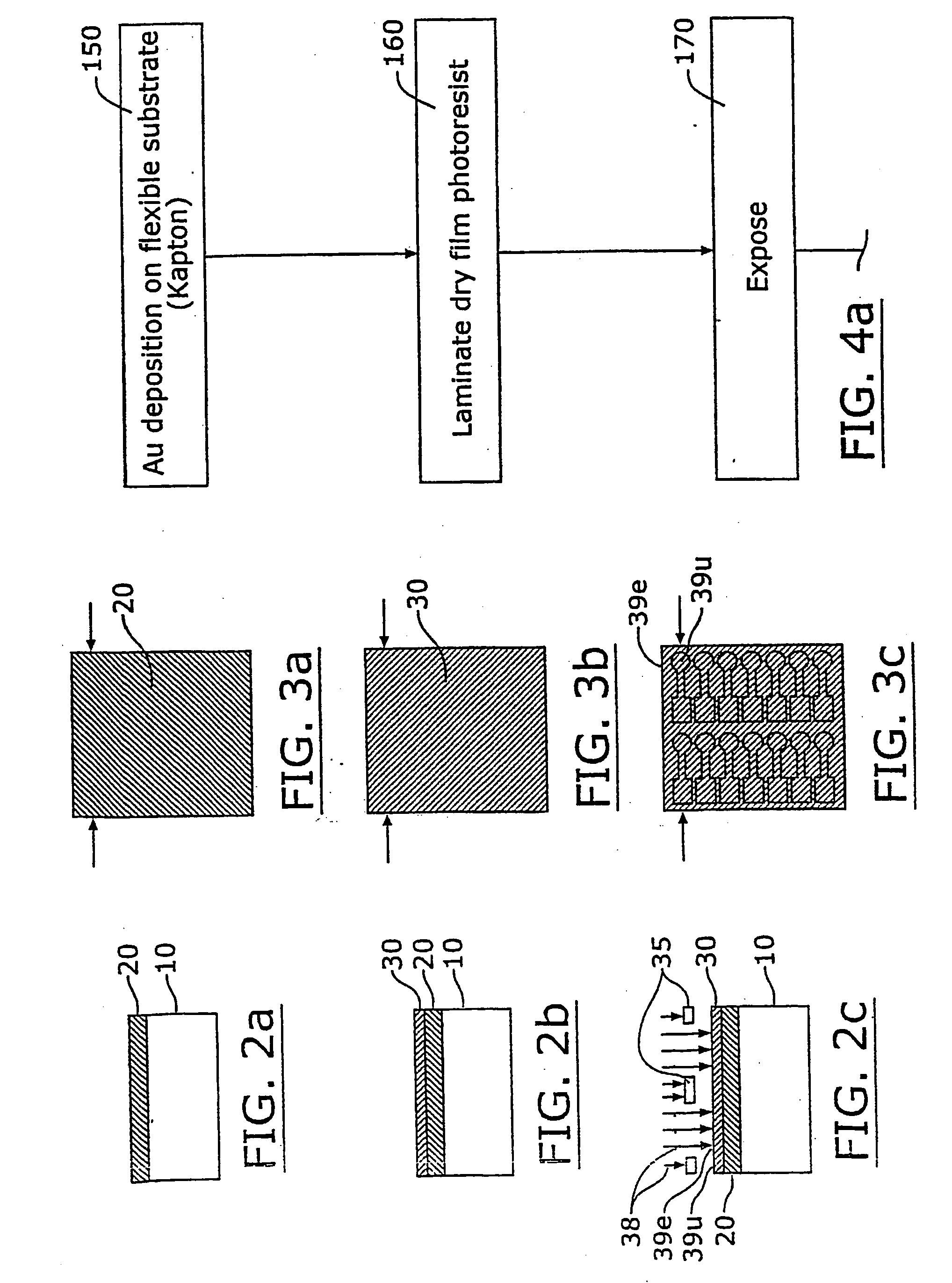
[0053] The following process was used to prepare an article according to embodiments of the invention. According to the method, a gold film or layer is deposited onto a flexible substrate formed of 7 mil thick Kaladex® film using a planar DC magnetron sputtering process and equipment operated Techni-Met Inc. (a roll coating company), located in Windsor, Conn. The thickness of the gold film can range from 30 to 200 nm, with a preferred thickness being about 100 nm. Seed layers of chromium or titanium can be sputtered between the substrate film and the gold layers to promote better adhesion of the gold to the substrate film; however, gold layers sputtered directly onto the substrate film without such seeding can exhibit sufficient adhesion. Plasma treatment of substrate surface can improve the adhesion of gold.

[0054] After the gold was applied to the flexible substrate, a dry film photopolymer resist was laminated to the gold / substrate film. A dry film resist such as that sold under ...


PUM

PropertyMeasurementUnit
Thicknessaaaaaaaaaa
Flexibilityaaaaaaaaaa
Photosensitivityaaaaaaaaaa

Abstract

Methods for fabricating a plurality of sensors on a flexible substrate, with each sensor having associated electrodes and at least one well include (a) providing a flexible substrate material layer having a surface area defined by a length and width thereof; (b) forming a plurality of sensor elements onto the flexible substrate material layer, each sensor element comprising at least one metallic electrode; (c) disposing at least one coverlay sheet layer over the flexible substrate sandwiching the sensor elements therebetween; (d) laminating the at least one coverlay sheet layer having an associated thickness to the flexible substrate; and (e) removing predetermined regions of the laminated coverlay sheet layer from the flexible substrate layer to expose a portion of the underlying metallic pattern of each sensor element and to define a well with a depth corresponding to the thickness of the coverlay sheet layer. The disclosure also describes multi-layer laminated flexible sensors and arrays of sensors with wells having enhanced well capacity and / or depth.

Description

RELATED APPLICATIONS [0001] This application claims priority to U.S. Provisional Application Ser. No. 60 / 332,194, filed Nov. 16, 2001, the contents of which are hereby incorporated by reference as if recited in fill herein.GOVERNMENT RIGHTS [0002] Work related to the invention was sponsored by the NSF CECT under Grant No. CDR-8622201. The United States Government has certain rights to this invention.FIELD OF THE INVENTION [0003] The present invention relates to methods for fabricating electrochemical sensors or wells on flexible substrates and associated products. The products may be particularly suitable for use as disposable biomedical sensors. BACKGROUND OF THE INVENTION [0004] Probes or sensors used in medical diagnostic or evaluation procedures often use electrochemical detection provided by dry or fluid / liquid chemistries / electrolytes placed on top of electrodes formed of precious metals (gold, platinum, etc). The probes or sensors can employ chemistries / electrolytes such as s...

Claims


Application Information

Patent Timeline
IPC IPC(8): B44C1/22G01N27/30G01N27/403H01L31/00H05K3/00H05K3/28
CPCH05K3/0023G01N27/3272H05K3/281
Inventor UFER, STEFANWILSEY, CHRISTOPHER D.
Owner ROCHE DIABETES CARE INC
Learn More