Detection of articles having substantially rectangular cross-sections
a technology of substantially rectangular cross-sections and detection objects, which is applied in the field of remote detection of articles having substantially rectangular cross-sections, can solve the problems of limited sensitivity of orientation-dependent sensitivity and distance over which detection of articles is possible, and limited sensing distance of prior art technologies. , to achieve the effect of less expensive construction, easy installation and use, and forgiving operation
- Summary
- Abstract
- Description
- Claims
- Application Information
AI Technical Summary
Benefits of technology
Problems solved by technology
Method used
Image
Examples
example 1
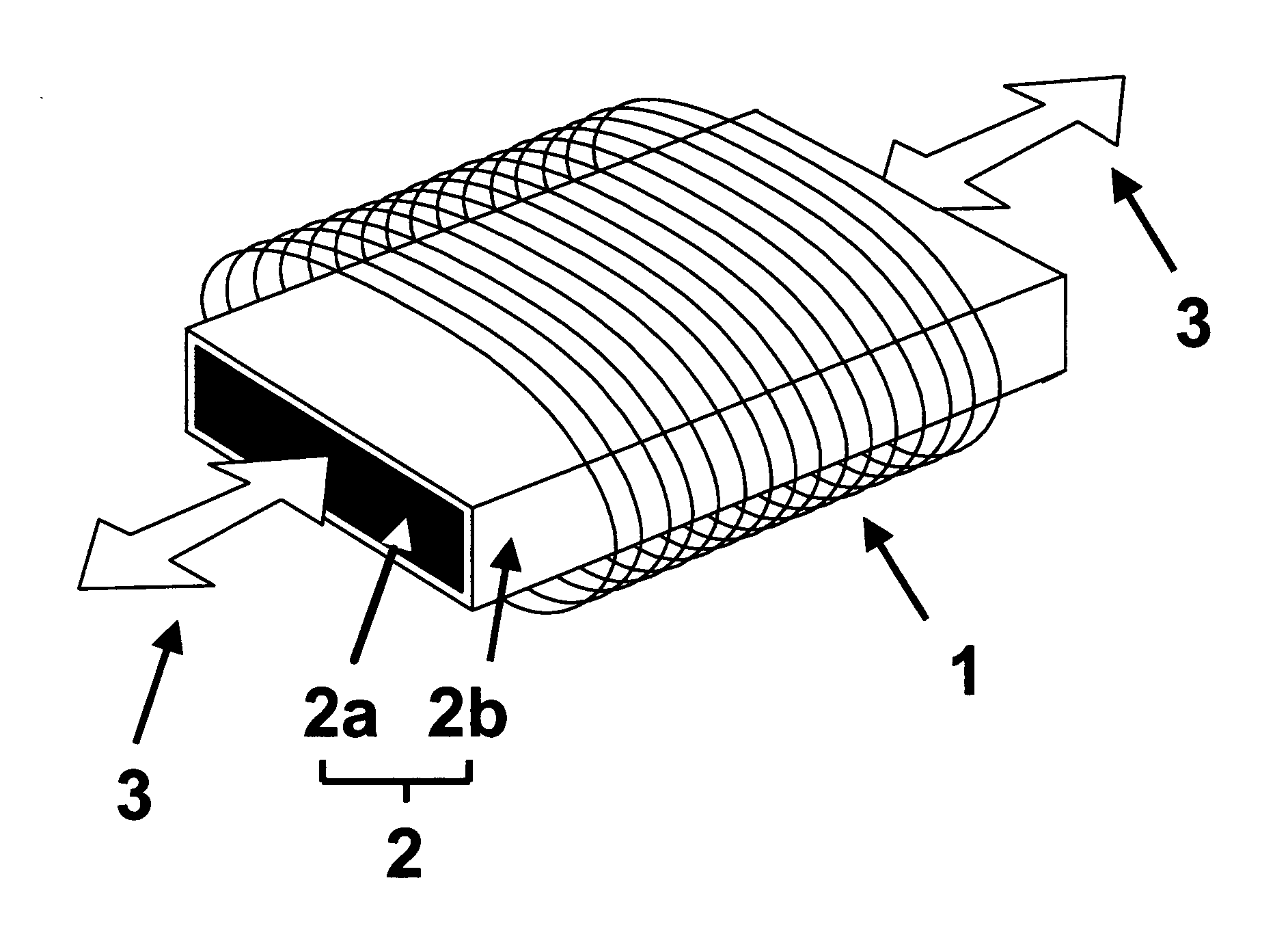
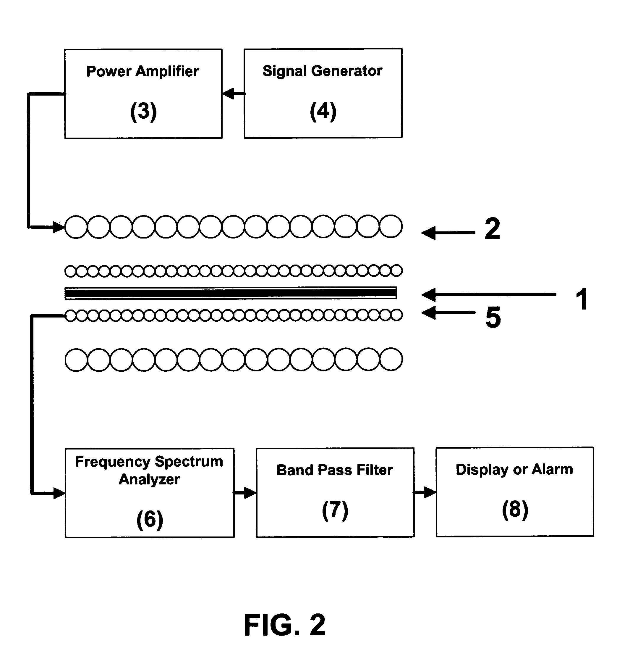
[0032] A magnetic detection system comprised essentially of two concentric wound wire solenoids was constructed, as schematically represented in FIG. 2. The magnetic tickler coil is wound onto a PVC tube that is 46 cm long and 5 cm in diameter. There are 150 turns of 1.6-mm diameter insulated copper wire wound about this tube to create the magnetic field tickler coil. The sensing coil is wound onto a PVC tube that is 7.5 cm long and 1.9 cm in diameter. There are 600 turns of 0.4-mm diameter insulated copper wire wound about this tube to create the magnetic field sensing coil. The elements of the electrical circuitry used are shown in FIG. 2. A sample to be tested for the presence and relative magnitude of magnetic harmonics is inserted into the magnetic field sensing coil, which is then inserted into the magnetic tickler field coil. For ease of handling, glass-coated amorphous microwire samples tested while affixed to a paper strip with double-stick adhesive tape. This ensures that ...
example 2
[0034] Following the same procedures and using the same equipment as in Example 1, a glass-coated microwire with an amorphous alloy core having nominal chemistry CO68.18Fe4.32B15Si12.5 was tested using the magnetic detection system. No harmonics were observed when subjected to the same test protocol as before. It is believed that this difference in performance between the two glass-coated amorphous alloy microwire samples tested is related to the magnetic domain structure of these two kinds of microwire. In the case of the Fe77.5B15Si7.5 glass-coated microwire, the magnetic domain structure is comprised of a single domain aligned along the center of the microwire, surrounded by a torus of small, radial domains of alternating polarity. In contrast, the CO68.18Fe4.32B15Si12.5 glass-coated microwire is comprised of a magnetic center that is not aligned along the center of the microwire. An important distinction between these two kinds of domain structures is that the Fe77.5B15Si7.5 sam...
example 3
[0035] Glass-coated amorphous alloy microwire samples were prepared by affixing four 7.5 cm lengths spaced about 1 mm apart onto a paper substrate using double-sided adhesive tape. This sample was then taken to the Flanders, N.J. Blockbuster store, in which Sensormatic electronic article surveillance gates are installed. I was given permission to do some testing with this magnetic detection system. The sample prepared was found to sound the alarm whenever the microwires therein were held simultaneously horizontally and perpendicular to the direction of walking through the Blockbuster detection gate. It was found, however, that that alarm was not sounded when the sample deviated by more than about 30 degrees from the orientation just described. An important result of this example is that a commercial magnetic detection system, even though not optimized for the detection of glass-coated amorphous microwire, was successful in detecting the presence of a sample made up of microwire leng...
PUM
 Abstract
Description
Claims
Application Information
 - R&D
- Intellectual Property
- Life Sciences
- Materials
- Tech Scout
- Unparalleled Data Quality
- Higher Quality Content
- 60% Fewer Hallucinations
Browse by: Latest US Patents, China's latest patents, Technical Efficacy Thesaurus, Application Domain, Technology Topic, Popular Technical Reports.
© 2025 PatSnap. All rights reserved.Legal|Privacy policy|Modern Slavery Act Transparency Statement|Sitemap|About US| Contact US: help@patsnap.com


