System and method for motion compensation of image planes in color sequential displays

a motion compensation and image plane technology, applied in the field of color image displays, can solve the problems of increasing image presentation latency and/or memory requirements, artifacts may be generated, etc., and achieve the effects of reducing color break-up, avoiding various motion image artifacts, and improving perceived image quality

Inactive Publication Date: 2005-10-27
KONINKLIJKE PHILIPS ELECTRONICS NV
View PDF0 Cites 33 Cited by
  • Summary
  • Abstract
  • Description
  • Claims
  • Application Information

AI Technical Summary

Benefits of technology

[0025] Therefore, it is an object according to the present invention to provide a system and method for image compensation in an image display device in order to avoid various motion image artifacts, especially image color break-up and improve a perceived imaged quality.
[0026] It is a further object of the invention to provide a color sequential image display processor which reduces color break-up by estimating an optimal position of an image representation of a moving object or area based on a time of presentation and predicted or estimated motion characteristics.

Problems solved by technology

Higher order predictions, for example, require additional information, and may therefore increase image presentation latency and / or memory requirements.
However, portions of a moving foreground object may cover or uncover the background image.
Therefore, in spite of the use of intelligent algorithms, artifacts may be generated in this case as well.

Method used


Image

  • System and method for motion compensation of image planes in color sequential displays
  • System and method for motion compensation of image planes in color sequential displays
  • System and method for motion compensation of image planes in color sequential displays

Examples


Embodiment Construction

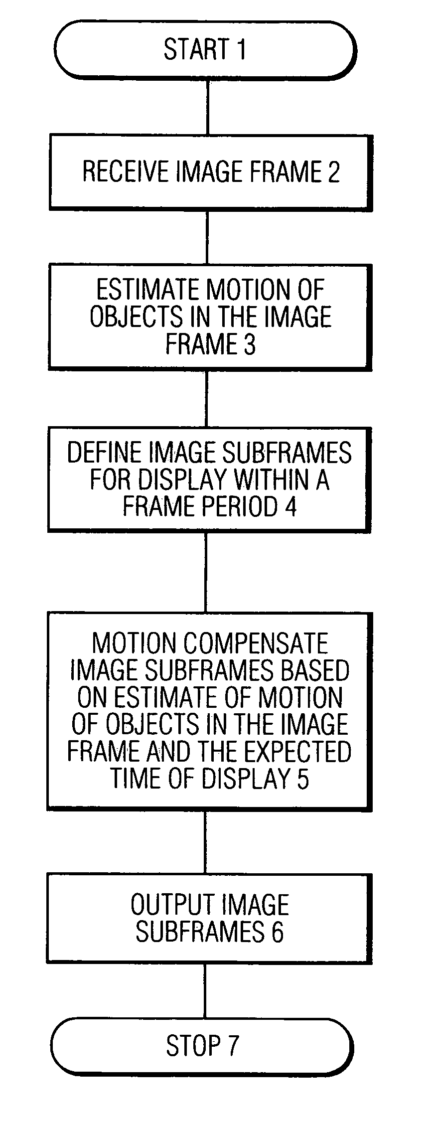
[0043] The invention will now be described by way of the drawings, in which corresponding reference numerals indicate corresponding structures in the figures.

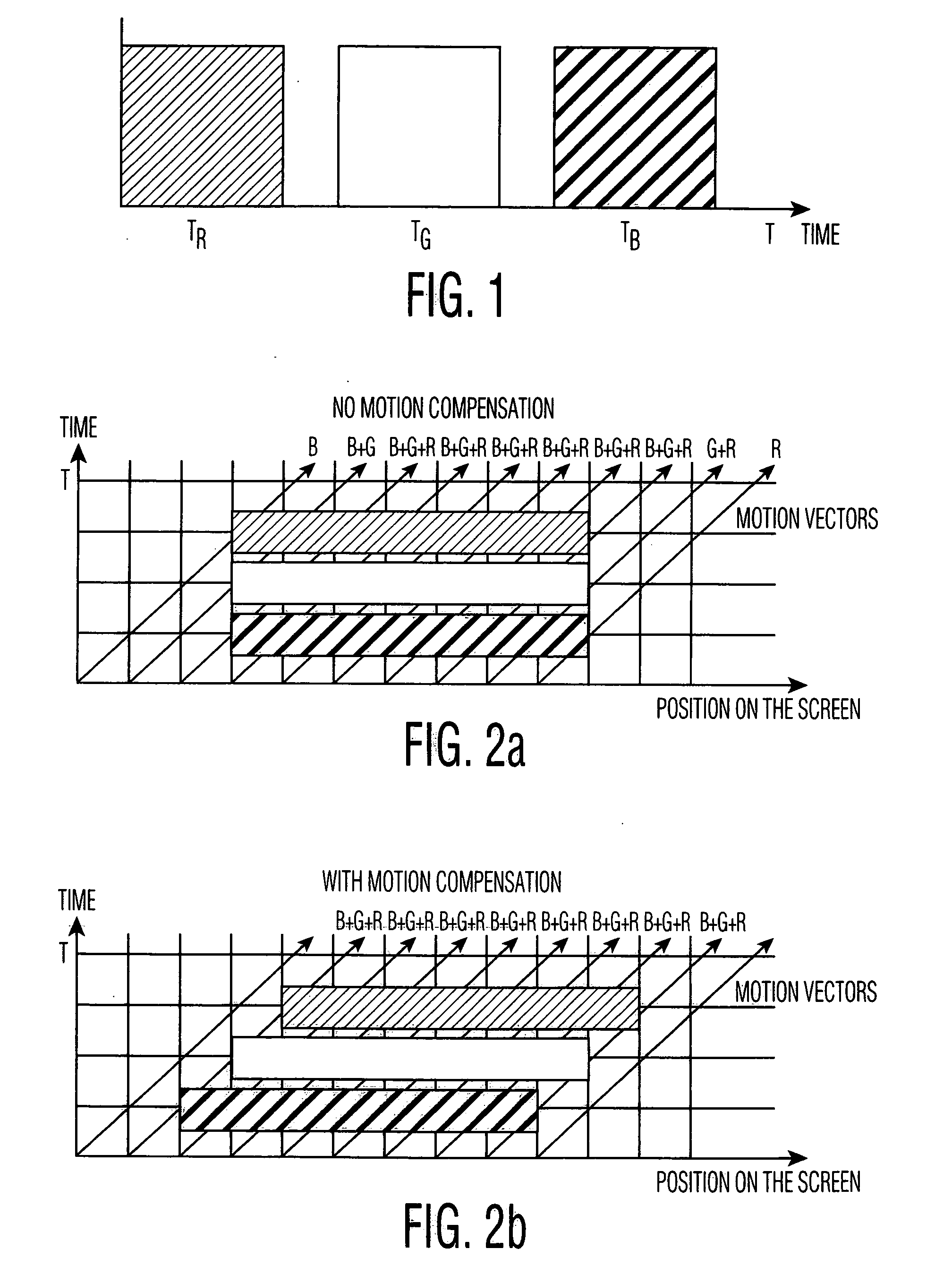
[0044] As shown in FIG. 2, a white (R+G+B) vertical bar 6 pixels wide is moving over the screen over a black background with a speed of 3 pixels per frame. The observer's eyes track the motion according to the speed and direction of the motion vectors. At the top of the motion vectors, the colors have been shown that are observed when tracking this motion. At the leading edge of the line, a blue and mix of blue and green pixel is being observed, while at the trailing edge a mix of green and red, and a red pixel can be seen. Motion compensation attempts to project the RGB data from one pixel on the motion vector. The result is that the same vertical bar is also shown in FIG. 2, and in this case only the white bar is seen.

[0045] The observed luminance is the sum of the observed color subframes, SF, thus, L⁡(k)=∑SF(1)

and is in...


PUM


Abstract

A system and method for motion compensation of color sequential displays, receiving a motion image data input, extracting an estimate of a motion of an image portion represented in said image data input with a motion estimator, and calculating, for a time instance of display of each image subframe of an image frame, a compensated representation for reducing display artifacts with a processor, wherein each subframe represents a different aspect of the image frame. The subframes are preferably different color planes of the image frame. The processor preferably performs a bilinear interpolation where the compensated image boundary does not fall on a display pixel boundary. The motion compensation algorithm is preferably robust in the face of erroneous motion vectors. The system and method is advantageously used in single panel liquid crystal display projection systems, although the techniques are applicable to various image display technologies.

Description

FIELD OF THE INVENTION [0001] The present invention relates to the field of color image displays, and more particularly to color displays in which the color image planes are separately updated or displayed. The invention also relates to compensation of motion images for artifacts introduced by a discrete time representation thereof. BACKGROUND OF THE INVENTION [0002] Color image displays are of two general types. In a first type, exemplified by a typical direct view cathode ray tube color display, all color image components are displayed simultaneously. Thus, an image model, e.g., a CCIR-601 signal, defines the luminance and chrominance of each image pixel at a particular time. The motion image is therefore presented as a time sequence of color image frames. [0003] In a second type of color image display, color image planes are displayed sequentially. This type of system is employed, for example, in certain single panel image projection systems, in which light of various colors sequ...

Claims


Application Information

Patent Timeline
Patent Type & Authority Applications(United States)
IPC IPC(8): G09G3/20H04N9/12G09G5/00G09G5/02G09G5/36H04N7/46H04N9/30H04N9/64
CPCG09G3/2003G09G2310/0235G09G2320/0261H04N19/577H04N9/30H04N9/646G09G2320/106G09G3/20
Inventor VAN DIJK, ROYSHIMIZU, JEFFREY A.
Owner KONINKLIJKE PHILIPS ELECTRONICS NV
Why Eureka
Try Eureka