Image display method, apparatus and program

a display method and image technology, applied in the field of image display methods and apparatuses, can solve the problems of difficult comparison between the two images, the observer's observation region is limited to the image area, and the image display each becomes too small for the observer, so as to achieve efficient comparative observation

Inactive Publication Date: 2005-10-27
FUJIFILM CORP +1
View PDF7 Cites 90 Cited by
  • Summary
  • Abstract
  • Description
  • Claims
  • Application Information

AI Technical Summary

Benefits of technology

[0010] The present invention has been developed in view of the circumstances described above, and it is an object of the present invention to provide an image display method, apparatus and program for implementing the method capable of facilitating an efficient comparative observation among local areas of a plurality of medical images corresponding with each other. The object of the present invention is achieved by providing an image display method, apparatus and program for implementing the method which, in performing a comparative observation among an image of a local area of a predetermined baseline image and images of corresponding regions of other comparison images corresponding to the local area, allows the observer to observe the images of the corresponding regions of comparison images not displayed on the screen, to observe the image of the local area and the images of the corresponding regions simultaneously, and to perform a comparative observation among the images of the local area and corresponding regions without requiring a relatively large shift of visual axes of the observer.

Problems solved by technology

In the former system, however, the observable regions are limited to those of the images displayed on the screen.
Consequently, where a large number of images are to be referenced, each of the images displayed on the screen becomes too small for the observer.
In addition, when the reference image is superimposed on top of the diagnostic region, the observer is not allowed to observe the image of the diagnostic region and the reference image simultaneously, or if the reference image is displayed on a separate screen, the comparison between the two images becomes difficult for the observer since the observer needs to shift the visual axes to a relatively large extent to observe the image of diagnostic region and the reference image.

Method used


Image

  • Image display method, apparatus and program
  • Image display method, apparatus and program
  • Image display method, apparatus and program

Examples


Embodiment Construction

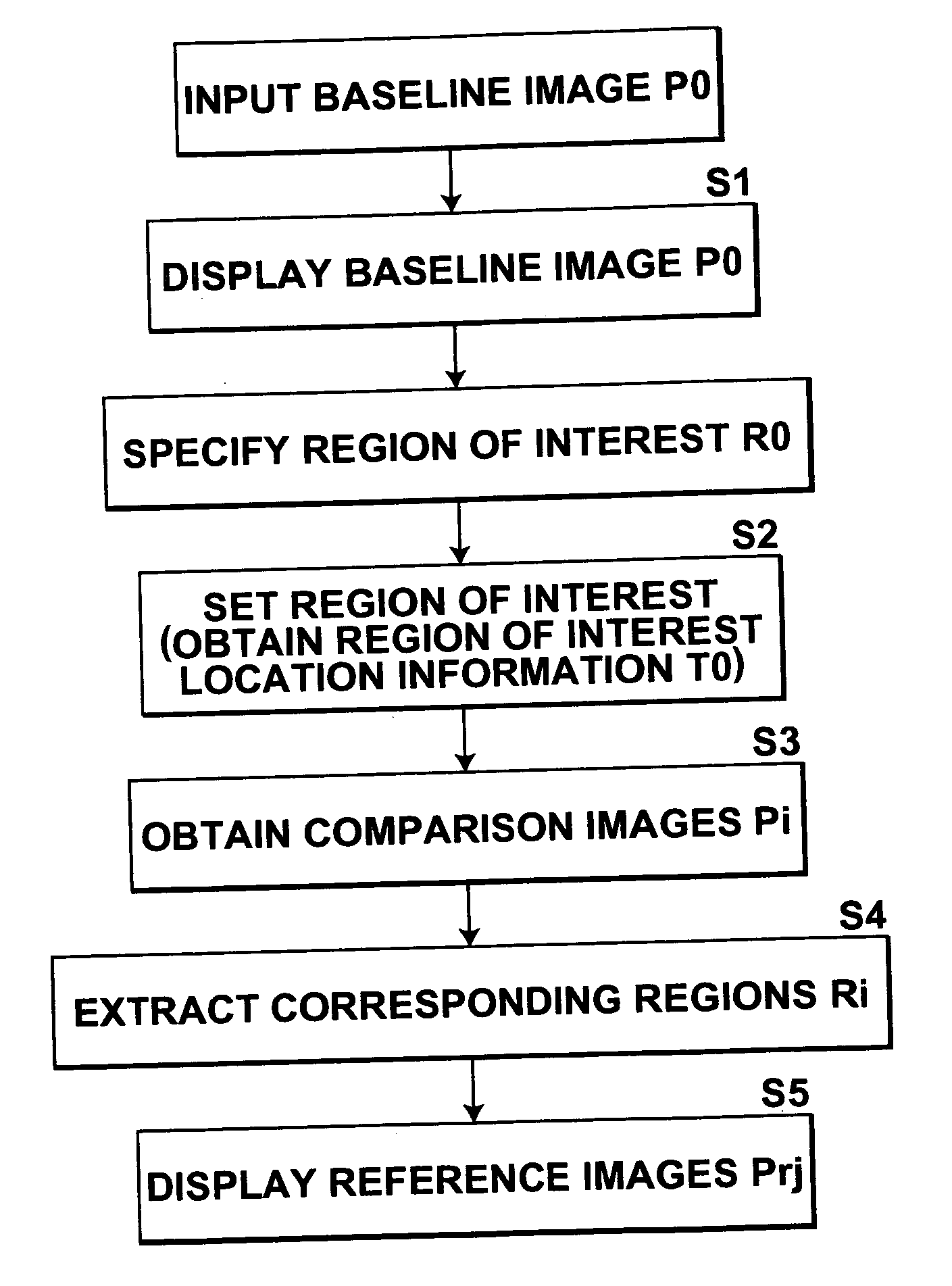
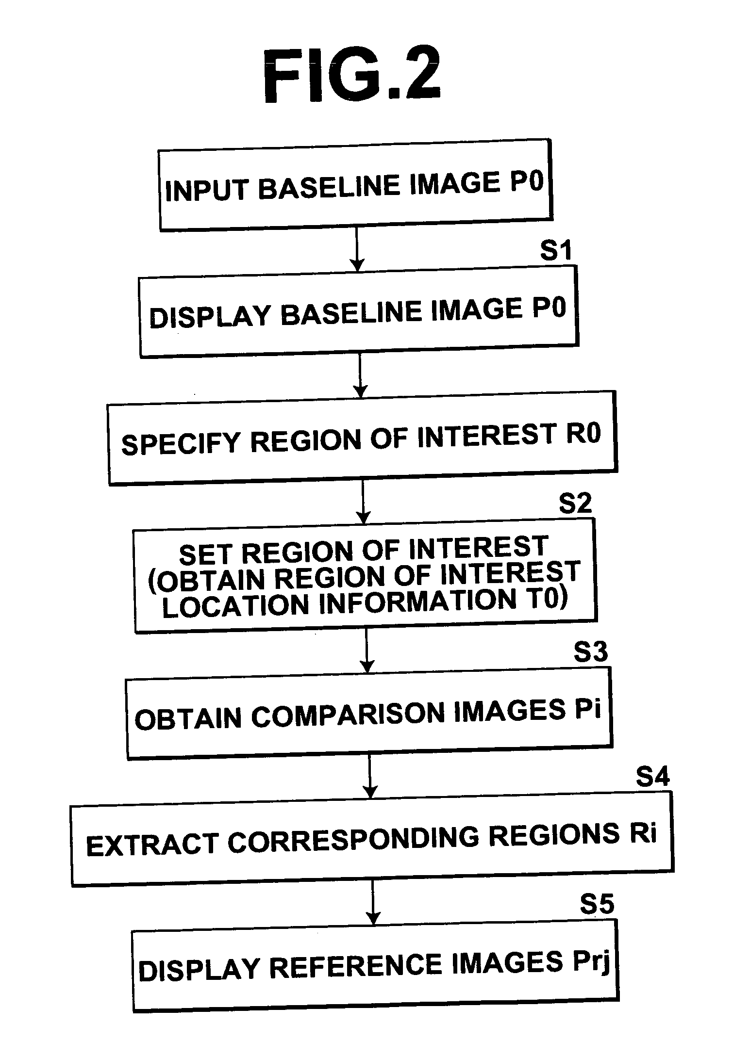
[0048] Hereinafter, an embodiment of the present invention will be described with reference to the accompanying drawings.

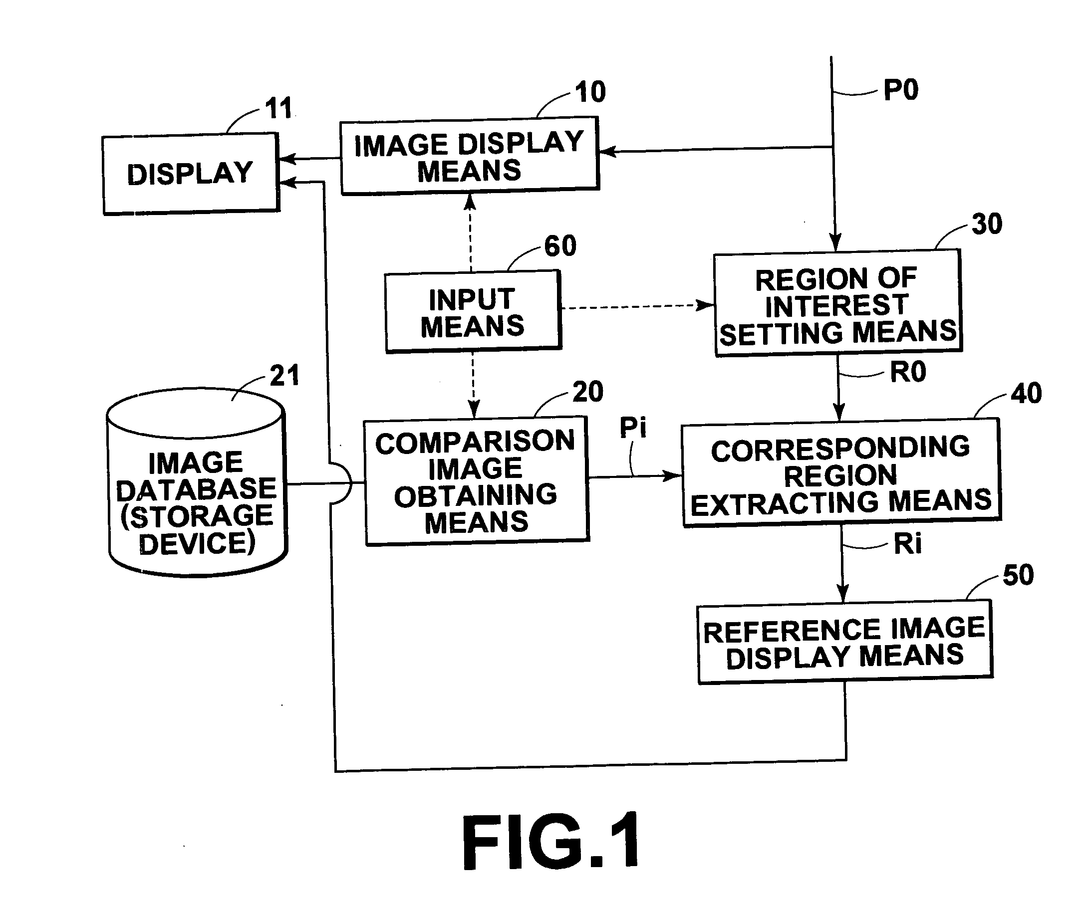
[0049]FIG. 1 is a schematic block diagram of an image display apparatus 100 according to an embodiment of the present invention, illustrating the configuration thereof.

[0050] The image display apparatus 100 shown in FIG. 1 comprises: an image display means 10 for displaying an inputted baseline image P0, which is a chest x-ray image representing a chest 1a of a patient 1, on a screen 11D of a display 11; comparison image obtaining means 20 for obtaining one or more comparison images Pi (i=1, 2, 3 . . . ), which are medical chest images different from the baseline image P0, from an image database (storage device) 21 storing multitudes of different medical chest images; a region of interest setting means 30 for setting a local area specified on the baseline image P0 displayed on the screen as a region of interest R0; a corresponding region extracting means 40 for ...


PUM


Abstract

In an image display apparatus, a method for performing an effective comparative image observation is provided for local areas that correspond with each other among a plurality of medical images. When a region of interest is specified on a baseline image displayed on the screen of a display, a corresponding region that corresponds to the region of interest is extracted from each of the comparison images obtained from an image database. Then, reference images, which are images of the corresponding regions and/or an image corresponding to the region of interest generated based on at least one of the images of the corresponding regions, are displayed at a place adjacent to the region of interest of the baseline image on the screen by arranging them side by side or switching them.

Description

BACKGROUND OF THE INVENTION [0001] 1. Field of the Invention [0002] The present invention relates to an image display method, apparatus and program for implementing the method. More specifically, the present invention is directed to an image display method, apparatus and program for implementing the method, which is suitable for use in comparative observation of local areas that correspond with each other among a plurality of medical images. [0003] 2. Description of the Related Art [0004] In the medical field, when giving a diagnosis by observing a medical image, such as the x-ray image, tomographic (CT) image, or the like, representing a predetermined area of a patient, a local area of the medical image is compared with a corresponding region on a time-series image obtained by imaging the same area of the same patient in the past, or that of the same modality image representing the same type of region of the other patient to check the probability of a new lesion being developed or ...

Claims


Application Information

Patent Timeline
Patent Type & Authority Applications(United States)
IPC IPC(8): G06K9/00G06T7/00
CPCG06T7/0012
Inventor NAKAMURA, KEIGO
Owner FUJIFILM CORP
Why Eureka
Try Eureka