Lubrication free connection

a technology of self-lubricating shaft and pivot pin, which is applied in the direction of combs, buttons, other domestic objects, etc., can solve the problems of constricting the internal diameter of the plastic sleeve, and achieve the effect of sufficient material for wear, increased adhesion, and inability to reduce the internal diameter

Inactive Publication Date: 2005-10-27
TRI MACK PLASTICS MFG
View PDF19 Cites 0 Cited by
  • Summary
  • Abstract
  • Description
  • Claims
  • Application Information

AI Technical Summary

Benefits of technology

[0005] Attachment of the self lubricating plastic bushing is achieved by insert injection molding, at high pressure and temperature, a plastic sleeve around the metal pin. To enhance adhesion and provide sufficient material for wear, the plastic is molded in a groove of a specific depth which has a knurled surface. The self lubricating bearing member is thus on the shaft which rotates in the metal housing. With this design, thermal expansion at elevated temperature results in contraction of the internal diameter of the plastic sleeve. Because the internal diameter cannot decrease, the forces holding the plastic sleeve on the pin are increased thereby preventing the sleeve bearing from loosening on the metal pin. To minimize the outside diameter expansion of the plastic bearing sleeve, a low coefficient of thermal expansion material with good self lubricating properties is used.

Problems solved by technology

With this design, thermal expansion at elevated temperature results in contraction of the internal diameter of the plastic sleeve.

Method used


Image

  • Lubrication free connection
  • Lubrication free connection
  • Lubrication free connection

Examples


Embodiment Construction

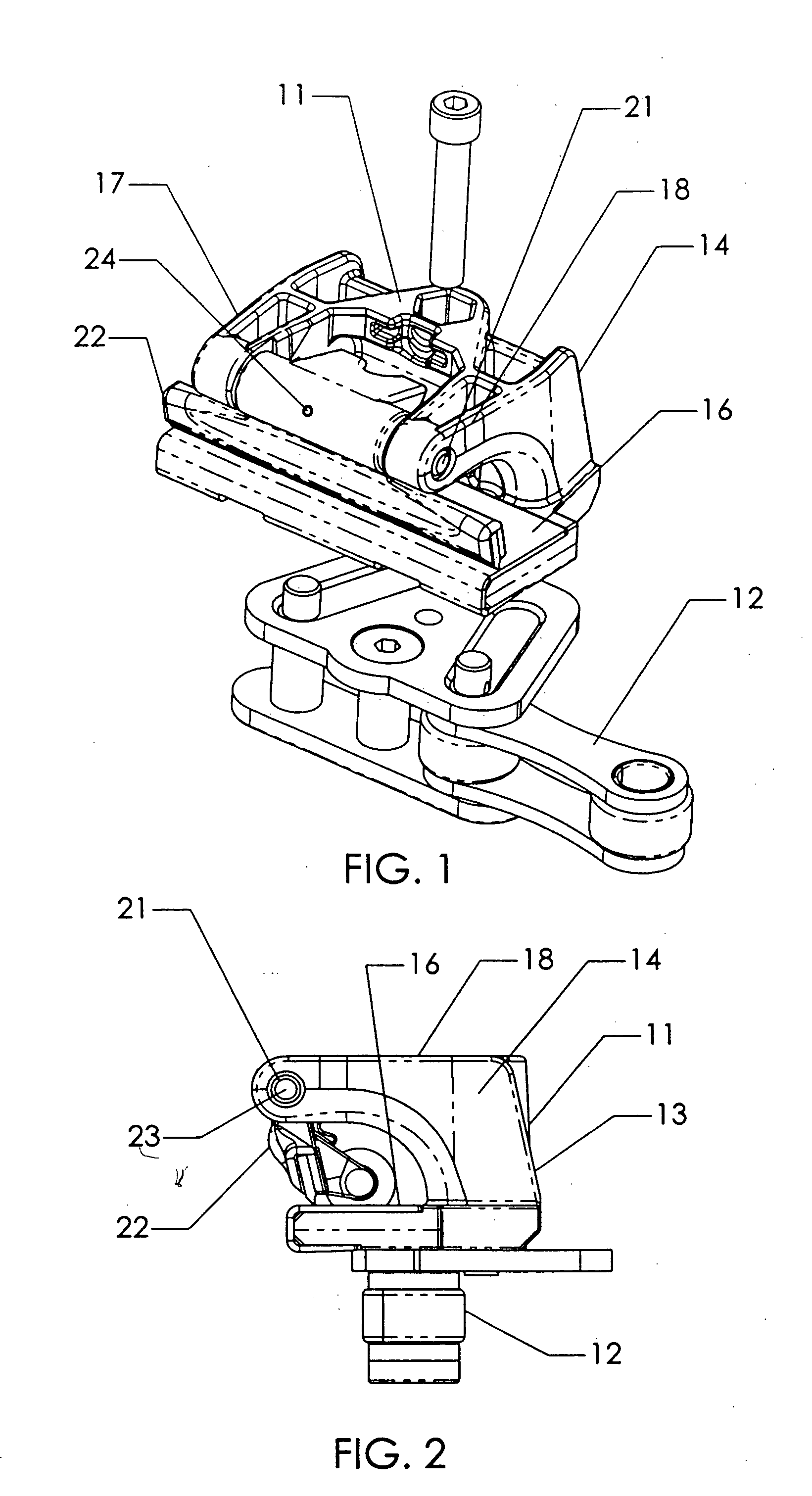
[0018] Referring to FIGS. 1 and 2, the invention is illustrated in a tenter clip 11 which with other clips, are connected in series by a link chain 12 thus providing a tenter chain 13. Tenter chains are provided in opposing pairs to grip the edge of a continuous web of flat material such as woven cloth and to simultaneously stretch the material in a transverse direction while conveying it through a process oven as a finishing operation to its manufacture.

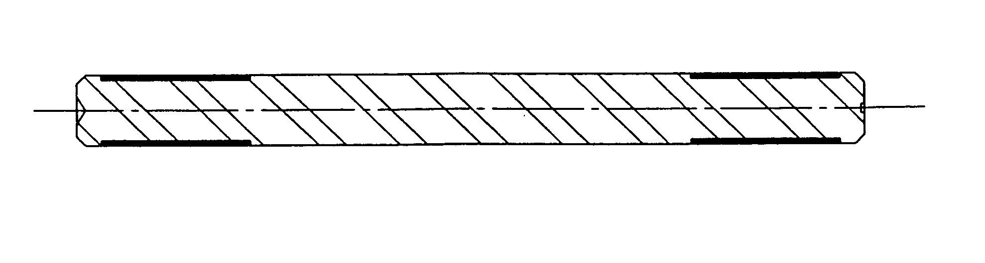
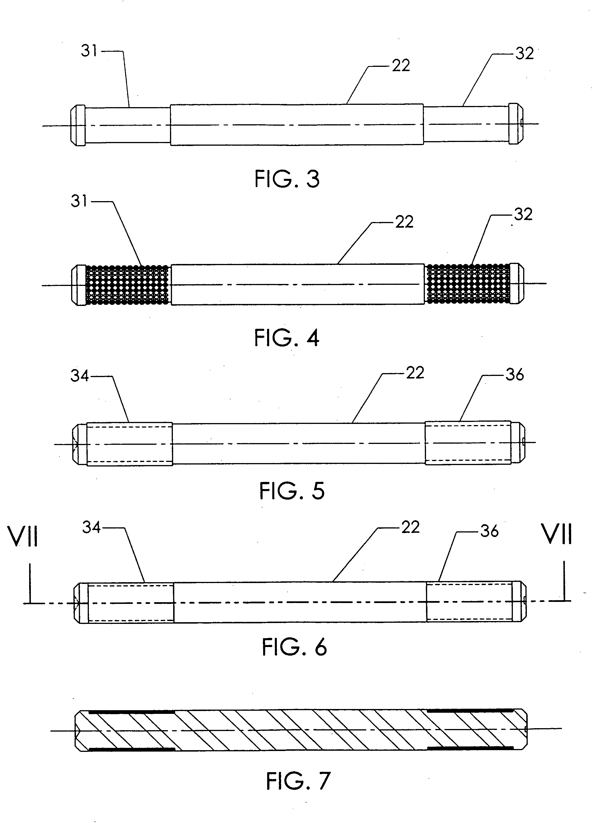
[0019] The tenter clip 11 is a clamping device which includes a clip body 14 which is open on one side with a surface 16 for supporting web material being fed into it. The clip body 14 includes a pair of support arms 17, 18 pivotally supporting a pivot pin 21 for a jaw 22. The pivotable jaw 22 is operated by an external mechanism, not shown, to allow entry and exit of the web material. The jaw 22, and the clip 11, are designed to automatically clamp and hold the web material. The jaws movement is a limited pivotal movement about th...


PUM

PropertyMeasurementUnit
temperatureaaaaaaaaaa
diameteraaaaaaaaaa
axial widthaaaaaaaaaa

Abstract

A tenter clip has a jaw pivot shaft having a pair of molded bearing surfaces of superior strength, wear resistance and stability under high temperature operating conditions. The method for manufacture of the jaw pivot shaft includes knurling recesses formed in the shaft prior to applying plastic bearing material to the recesses by injection molding and finishing machining the pin by centerless grinding.

Description

TECHNICAL FIELD [0001] This invention relates to the construction of a self lubricating shaft or pivot pin suitable for operating at high temperatures such as in tenter frame apparatus. BACKGROUND OF THE INVENTION [0002] U.S. Pat. No. 5,067,214 issued Nov. 26, 1991 to Christopher E. Hosmer and John F. Whaley for a Tenter Framer Apparatus and Method shows a self-lubricating bushing made of a polyamide resin. [0003] U.S. Pat. No. 5,797,172 issued Aug. 25, 1998 to Christopher Eugene Hosmer for a Tenter Frame and Method discloses tenter frame apparatus of the type in which this invention has particular application. [0004] Conventional self lubricating friction or wear devices such as bushings and / or plain bearings are typically composed of a metal housing in which a plain plastic bushing is inserted and secured in a manner preventing rotation of the bushing. Typically a metal shaft is carried in the interior diameter of the bushing. In the case of a tenter frame clip jaw application the...

Claims


Application Information

Patent Timeline
Patent Type & Authority Applications(United States)
IPC IPC(8): B21D53/10B23P15/00B29CB29C45/14D06C3/04F16C11/04F16C33/04F16C33/20F16J1/16
CPCB23P15/003B29C45/14336F16C11/045D06C3/04B29C45/14549F16C2340/00B21D53/10F16C33/04F16C33/20
Inventor HOSMER, CHRISTOPHER EUGENEMEDEIROS, ANTHONY C.MACK,, EDWARD J. II
Owner TRI MACK PLASTICS MFG
Why Eureka
Try Eureka