Bearing apparatus for supporting pinion shaft and pinion shaft support apparatus

Inactive Publication Date: 2005-10-27
JTEKT CORP
View PDF10 Cites 20 Cited by
  • Summary
  • Abstract
  • Description
  • Claims
  • Application Information

AI Technical Summary

Benefits of technology

[0009] In this case, rolling resistance of the double row angular contact ball bearing with vertex of contact angles outside of bearing is smaller compared with that of a tapered roller bearing, thereby giving the advantage of reducing torque. Moreover, the double row angular contact ball bearing with vertex of contact angles outside of bearing is configured so as to be sealed with the seals to be lubricated by the grease, so that oil in a target apparatus for use of the pinion shaft is not introduced inside the bearing, thereby enabling to clear up the problems relevant to the oil which have been pointed out in the conventional example.
[0011] A contact angle of said ball may be set to be preferably not less than 30 degrees and not more than 45 degrees. Preferably, a radius of curvature of each raceway surface of said outer ring may be set to be not less than 51.0% and not more than 52% of the ball diameter, and a radius of curvature of the raceway surface of each of said inner ring may also be set to be not less than 50.2% and not more than 51.2% of the ball diameter, respectively. When the contact angle of the double row angular contact ball bearing with vertex of contact angles outside of bearing, and the radius of curvature of the raceway surface are specified so as to be different from those of a typical standard item like this, load carrying capacity and durability can be improved.
[0012] An outer peripheral portion of said each seal is preferably fixed to the two counter bores of said outer ring, and may be configured so as to comprise a lip portion at an inner periphery having a shape for contacting to each shoulder portion of said two inner rings, and being able to be opened towards the outside of the bearing. In this case, the seal is a particularly superior type for preventing foreign substances from entering the inside from the outside of the bearing, thereby giving the advantage of stabilizing a behavior of the grease filled inside the bearing.
[0016] In this case, the double row angular contact ball bearing with vertex of contact angles outside of bearing is equivalent to the bearing apparatus for supporting the pinion shaft mentioned above, thereby making it possible to obtain a function and an effect in a matter similar to the above. Moreover, the pinion shaft and the double row angular contact ball bearing with vertex of contact angles outside of bearing as the bearing apparatus for supporting the pinion shaft are unitized, so that time and effort in incorporating it in a target for use is reduced, thereby making it possible to improve assembly performance.

Problems solved by technology

However, in both of the bearing apparatuses for supporting the pinion shaft described above, since the tapered roller bearing is employed, there exists a limitation in torque reduction.
In addition to that, in the case of the bearing apparatus for supporting the pinion shaft being used for the transfer, since a central shaft line of the pinion shaft is arranged upper than a central position of a transfer case, it may be pointed out that the oil in the case does not easily reach the inside of the bearing apparatus for supporting the pinion shaft.
On the other hand, in the case of the bearing apparatus for supporting the pinion shaft being used for the differential, since a central shaft line of the pinion shaft is arranged lower than a central position of the transfer case, the oil is introduced excessively, so that there is pointed out disadvantages in achieving torque reduction such that stirring resistance of the oil is increased and foreign substances in the oil are bit between a tapered roller and a raceway surface.

Method used


Image

  • Bearing apparatus for supporting pinion shaft and pinion shaft support apparatus
  • Bearing apparatus for supporting pinion shaft and pinion shaft support apparatus
  • Bearing apparatus for supporting pinion shaft and pinion shaft support apparatus

Examples


Embodiment Construction

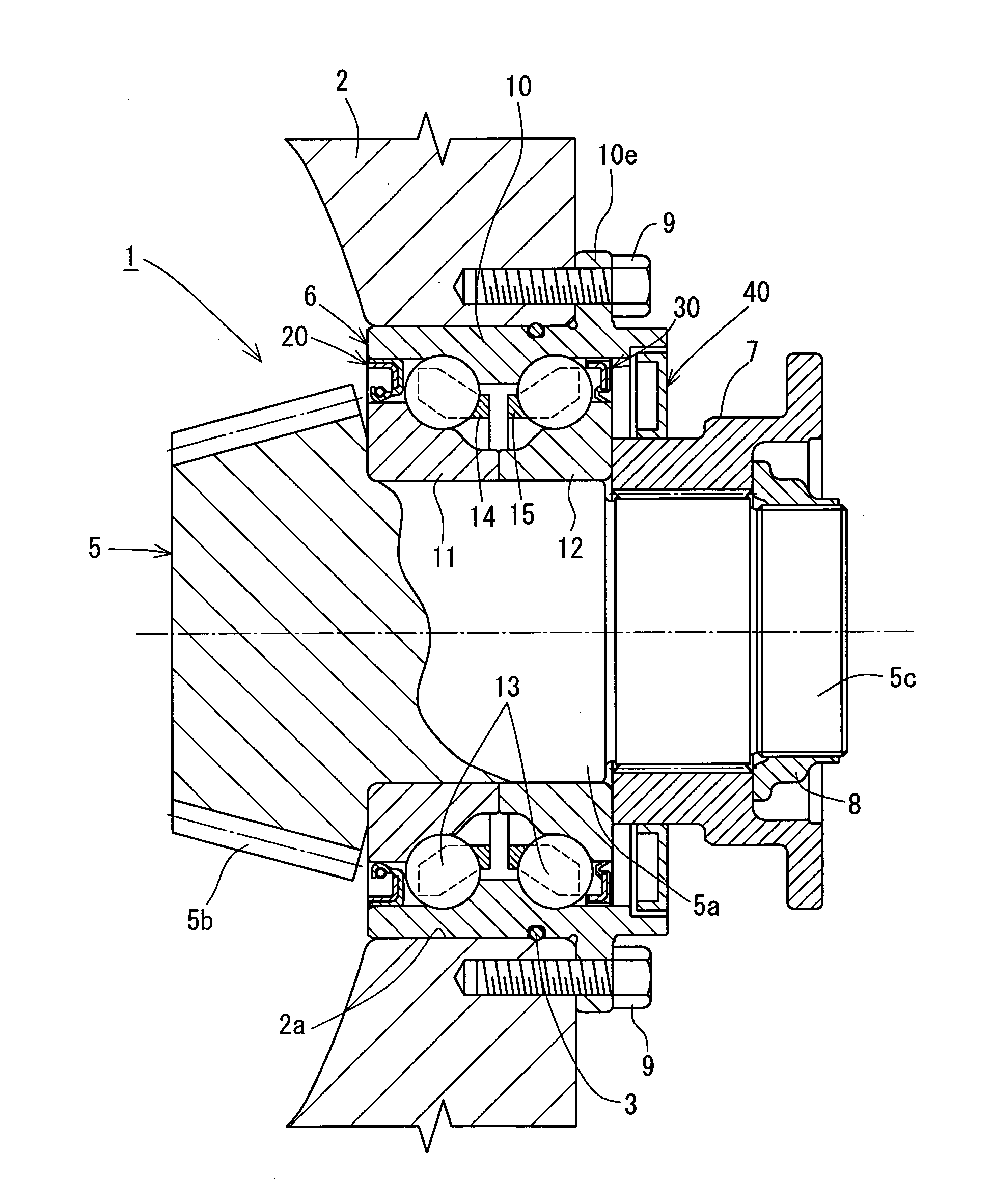
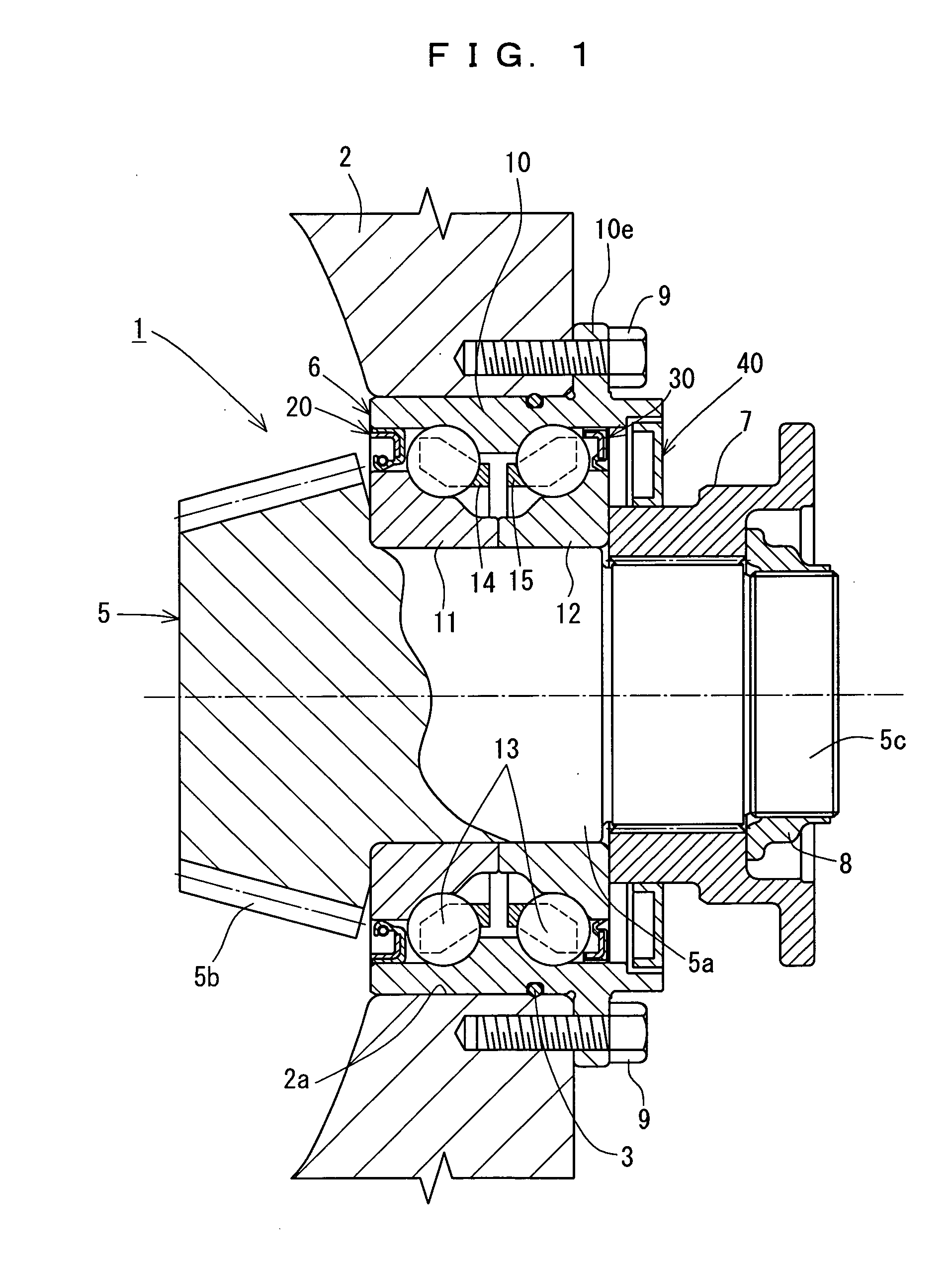
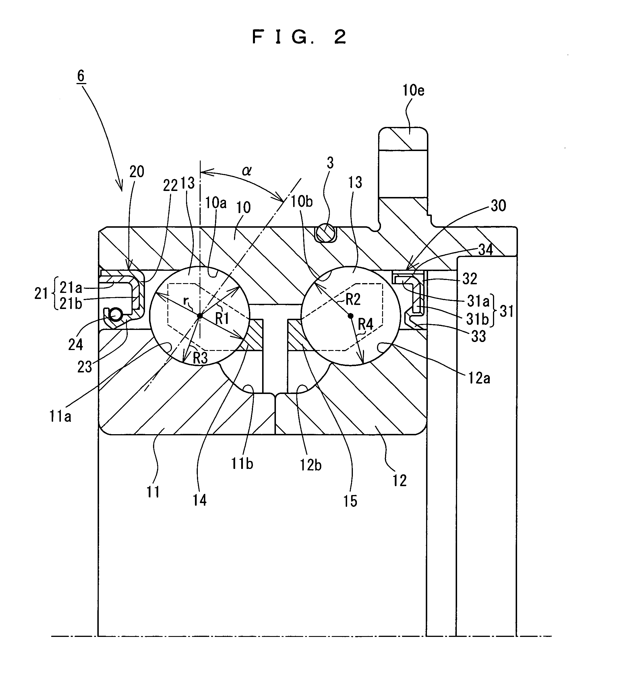
[0022] Referring to FIG. 1 through FIG. 3, description will be made of a preferred embodiment of the present invention. A pinion shaft support apparatus 1 illustrated in the drawings is incorporated in a case 2 of a transfer or a differential, and comprises a pinion shaft 5, a double row angular contact ball bearing with vertex of contact angles outside of bearing 6, a coupling sleeve 7, and a nut 8. Incidentally, the double row angular contact ball bearing with vertex of contact angles outside of bearing 6 is equivalent to a bearing apparatus for supporting a pinion shaft.

[0023] A pinion gear 5b is formed at one end of a shank portion 5a of the pinion shaft 5 in a shaft direction, and a screw shaft portion 5c is formed at the other end thereof in the shaft direction, respectively. The double row angular contact ball bearing with vertex of contact angles outside of bearing 6 is attached to the outside of the shank portion 5a of this pinion shaft 5, and the coupling sleeve 7 is spli...


PUM


Abstract

A double row angular contact ball bearing with vertex of contact angles outside of bearing 6 is employed for supporting a pinion shaft 5, and an internal space of the bearing 6 is also sealed with seals 20 and 30 equipped at both ends thereof in a shaft direction, so that grease is filled in this sealed bearing internal space. In this case, oil being used for a target apparatus for use of the pinion shaft 5 is not introduced inside the bearing 6, so that problems which have been generated in a conventional example where said oil has been introduced inside the bearing 6 can be cleared up.

Description

FIELD OF THE INVENTION [0001] The present invention relates to a bearing apparatus for supporting a pinion shaft and a pinion shaft support apparatus. DESCRIPTION OF THE PRIOR ART [0002] As a bearing apparatus for supporting a pinion shaft for rotatably supporting the pinion shaft incorporated in a transfer, a differential, or the like mounted on a vehicle, a bearing apparatus using two single row tapered roller bearings (refer to Japanese Patent Application Laid-Open No. 10-220468) and a bearing apparatus in which a single row tapered roller bearing and a single row angular contact ball bearing are integrated (refer to Japanese Patent Application Laid-Open No. 53-74653) are conventionally employed. [0003] For both of the bearing apparatuses for supporting the pinion shaft as described above, a pinion gear side thereof is in an opened state without being provided with a seal, and lubrication is performed using oil accommodated inside the transfer or the differential. [0004] In the t...

Claims


Application Information

Patent Timeline
IPC IPC(8): F16C19/18F16C33/66F16C33/78F16C35/067F16H48/42F16H57/021F16H57/037
CPCF16C19/184F16C33/6614F16C33/6633F16C33/7853F16C33/583F16H57/021F16H2048/423F16C33/726F16C2361/61F16C35/067F16C33/581F16C33/6603F16C2226/60F16H57/037
Inventor KAWAMURA, MOTOSHIIWAWAKI, TAKESHIYOKOTA, KUNIHIKO
Owner JTEKT CORP
Why Eureka
Try Eureka