Bone fasteners and method for stabilizing vertebral bone facets using the bone fasteners

a bone facets and bone fastener technology, applied in the field of bone fasteners, can solve the problems of screw loosening, inability to secure the plate to the bone or vertebrae, and inability to obtain bi-cortical purchase, etc., and achieve the effects of less invasiveness, less time consuming, and simple structur

Inactive Publication Date: 2005-10-27
WARSAW ORTHOPEDIC INC
View PDF40 Cites 181 Cited by
  • Summary
  • Abstract
  • Description
  • Claims
  • Application Information

AI Technical Summary

Benefits of technology

[0017] It is, therefore, an object of the invention to provide a fastener configured to have a structure providing for a less invasive and less time consuming procedure directed to stabilizing adjacent vertebrae.
[0018] Still another object of the invention is to provide a fastener configured to have a simple structure ensuring its easy placement through the facets or surrounding the facets of the vertebrae to be fused.

Problems solved by technology

Accordingly, known screws have an elongated structure capable of bicortical purchase, otherwise the screws may loosen and fail to securely couple the plate to the bone or vertebrae.
Such screws typically do not obtain bi-cortical purchase and are therefore more susceptible to loosening.
It is a drawback of this solution that it is difficult to rigidly insert screws through the pedicles on into the vertebral bodies and at the same time position the pedicle screws in two planes in exactly such a manner that the axes of the receiving slits in the receiver parts in the vertical columns align such that the rod may be passed through the receiving slits without distortion of the screws.
Even with the advent of polyaxial screws, alignment of the receiving slits and contouring the rods to fit these slits remain a time consuming process.
A further drawback is the difficulty in properly positioning the screws within the pedicles.
This takes much skill on the part of the surgeon.
Compromising the integrity of the cortical walls of the pedicle as well as further penetration into the vertebral body of the vertebra could lead to neurological complications and eventual implant loosening.
Additionally, the implantation of a pedicle screw system is a very invasive procedure, whereby a large incision is made to expose multiple vertebral levels.
Still another drawback is that the holding power of pedicle screws greatly depends on the length and size of screw used.
However, as discussed above, using such screws that extend through the pedicle on into the vertebral bodies results in a more invasive and time-consuming procedure.
As a rule, natural distribution of axial loads is, however, disturbed as a result of implantation surgery.
There is concern that leaving so much ‘foreign’ material behind could be detrimental to the patient.

Method used


Image

  • Bone fasteners and method for stabilizing vertebral bone facets using the bone fasteners
  • Bone fasteners and method for stabilizing vertebral bone facets using the bone fasteners
  • Bone fasteners and method for stabilizing vertebral bone facets using the bone fasteners

Examples


Embodiment Construction

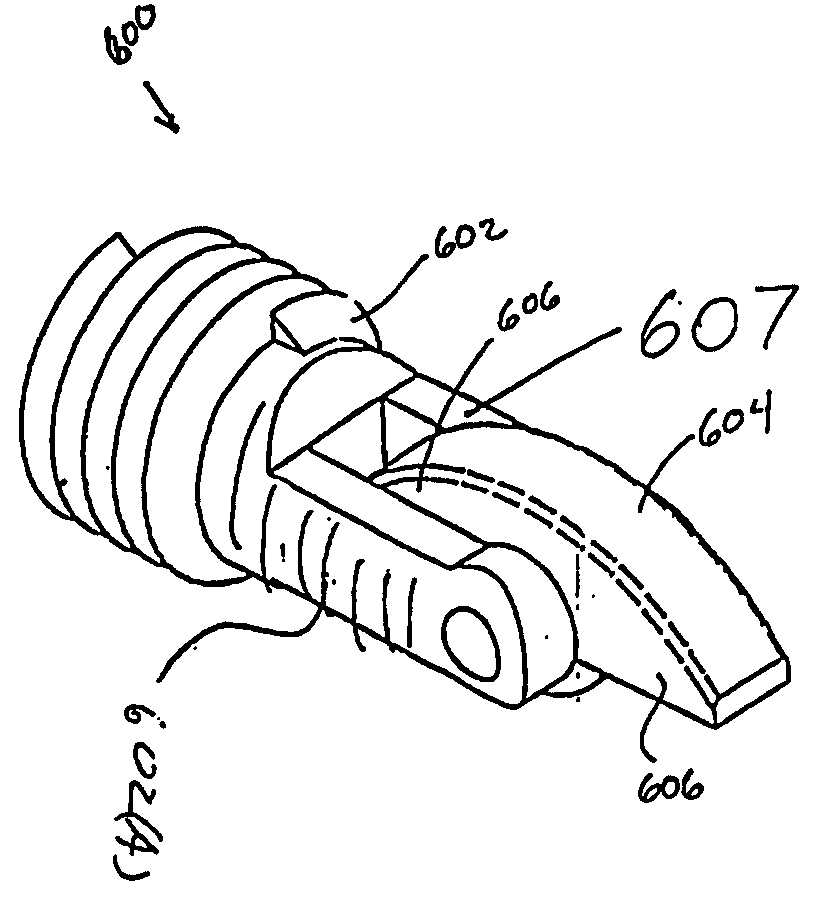
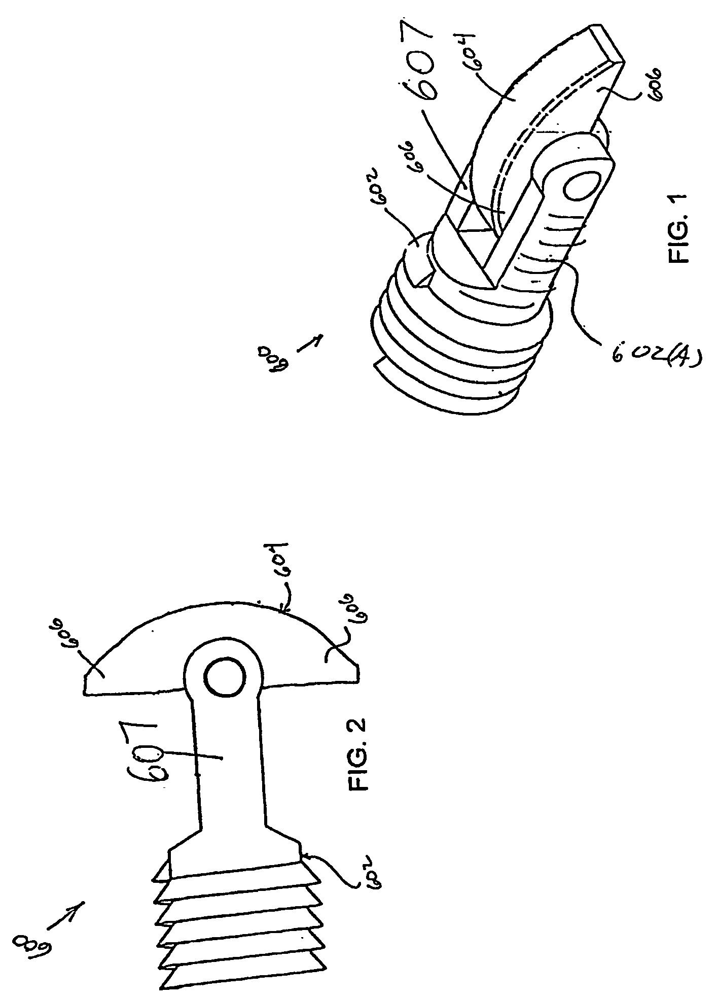
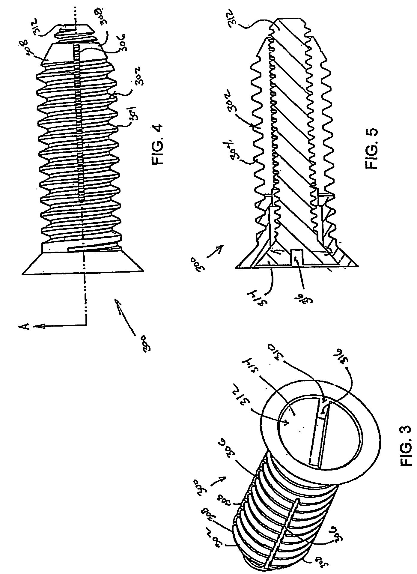
[0045] Referring to FIGS. 1 to 24, numerous embodiments of the inventive fastener can be successfully used in a variety of spinal implantation methods and is configured as a stabilization device directed to either secure bone segments or connect inferior and superior articular processes of superior and inferior adjacent vertebrae, respectively. In the latter, the rivet assembly can be used as supplemental posterior stabilization in a circumferential or 360 degree fusion or as a stand-alone device for cases with slight posterior instability.

[0046] A few methods of securing bone fragments or stabilizing the facets can be employed in association with the inventive assemblies. In the context of the facet stabilizing procedure, one of the methods provides for forming a small midline incision configured to expose the facets. Then, the inferior articular process of the superior vertebrae, the facet joint and the superior articular process of the inferior vertebrae are drilled so that a dr...


PUM


Abstract

A bone fastener for stabilizing bone fragments includes a single or multiple components coupleable with one another and displaceable to a locked position of the bone fastener.

Description

CROSS-REFERENCE TO RELATED APPLICATION [0001] This application is based on and claims priority to U.S. Provisional Application 60 / 343,810 filed Dec. 27, 2001.BACKGROUND [0002] 1. Technical Field [0003] The present disclosure relates to bone fastener. In particular, the present invention relates to a series of bone fasteners for use in stabilizing a pair of adjacent vertebral facets to one another and to a method of operating the inventive bone fasteners. [0004] 2. Background of Related Art [0005] It is often necessary to fix the facet joints of adjacent vertebrae to one another or to attach objects (e.g., bone plates, bone grafts, etc.) to a bone itself. For example, in repairing a fractured or damaged vertebra, it is often necessary to stabilize individual vertebrae in order to promote proper healing. Stabilization is often accomplished by fixing one vertebra to adjacent vertebrae or by using a bone plate, or pedicle screw and rod system, to interconnect adjacent or a series of ver...

Claims


Application Information

Patent Timeline
Patent Type & Authority Applications(United States)
IPC IPC(8): A61B17/00A61B17/68A61B17/70A61B17/88F16B19/10
CPCA61B17/68A61B17/683A61B17/688F16B19/1045A61B17/7064A61B2017/00867A61B17/70
Inventor CHOW, DAVIDGEREMAKIS, PERRYMARTZ, ERIK O.HOCHSCHULER, STEPHEN DROSENTHAL, DANIEL E.ANNUNZIATO, STEVENJOHNSTON, LARRY C.
Owner WARSAW ORTHOPEDIC INC
Why Eureka
Try Eureka