Hologram recording and reproducing apparatus and hologram reproducing apparatus

a recording and reproducing apparatus and a technology for reproducing apparatus, which are applied in the direction of digital signal error detection/correction, instruments, coding, etc., can solve the problems of reproducing signals, reproducing signals, reproducing signals, etc., and achieves high reliability and reduce decoding errors.

Inactive Publication Date: 2005-10-27
SAMSUNG ELECTRONICS CO LTD
View PDF6 Cites 22 Cited by
  • Summary
  • Abstract
  • Description
  • Claims
  • Application Information

AI Technical Summary

Benefits of technology

[0017] The present invention provides a hologram recording and reproducing apparatus and a hologram reproducing apparatus each of which provides a reduced decoding error and high reliability even when a signal-to-noise (S / N) ratio of reproducing signals is deteriorated due to various disturbances by performing a high-performance decoding process using a low-density parity check (LDPC) code.
[0023] According to the present invention described above, since the absolute value of the estimation data of the LDPC code is proportional to the difference in levels of the reproducing signal obtained from the respective pixels of the light receiver, the error correction ability of the LDPC code may be enhanced, so that a reduction of the bit error rate of the reproducing Reed-Solomon code is possible.
[0025] According to the present invention described above, since the high-performance signal processing with the LDPC code is performed using the estimation data calculated from the difference in levels of the reproducing signal, a reduction of the bit error rate of the reproducing Reed-Solomon code is possible compared to a case where the data are determined by considering only the relative size of the reproducing signal.
[0027] According to the present invention described above, when the reproducing block code does not correspond to a code word of the LDPC code, the estimation data of the reproducing block code is not used for the encoding process of the LDPC code, so that prevention of deterioration of the decoding performance due to erroneous estimation data is possible.

Problems solved by technology

However, a recording density of data in the plane of the optical disk is restricted by a diffractive limit of light.
This is due to the fact that the levels of the reproducing signals are changed due to various disturbances, such as media noise, system noise, interference between codes, cross-talk, deviation in pixel position, etc., in the hologram recording and reproducing apparatus.
However, in an actual hologram recording and reproducing apparatus, the signal-to-noise (S / N) ratio of the reproducing signals may deteriorate relatively easily due to various disturbances such as media noise, system noise, interference between codes, cross-talk, deviation in pixel position, etc.
For this reason, a decoding error of the reproducing Reed-Solomon code r often happens and the bit error rate often deteriorates to, for example, 1×10⁻².
Since the block code is decoded based only on the relative level of the reproducing signal p having a multi-valued level, the decoding error is often generated when the disturbance of the level of the reproducing signal p causes large variations in the reproducing signal p.

Method used


Image

  • Hologram recording and reproducing apparatus and hologram reproducing apparatus
  • Hologram recording and reproducing apparatus and hologram reproducing apparatus
  • Hologram recording and reproducing apparatus and hologram reproducing apparatus

Examples


first embodiment

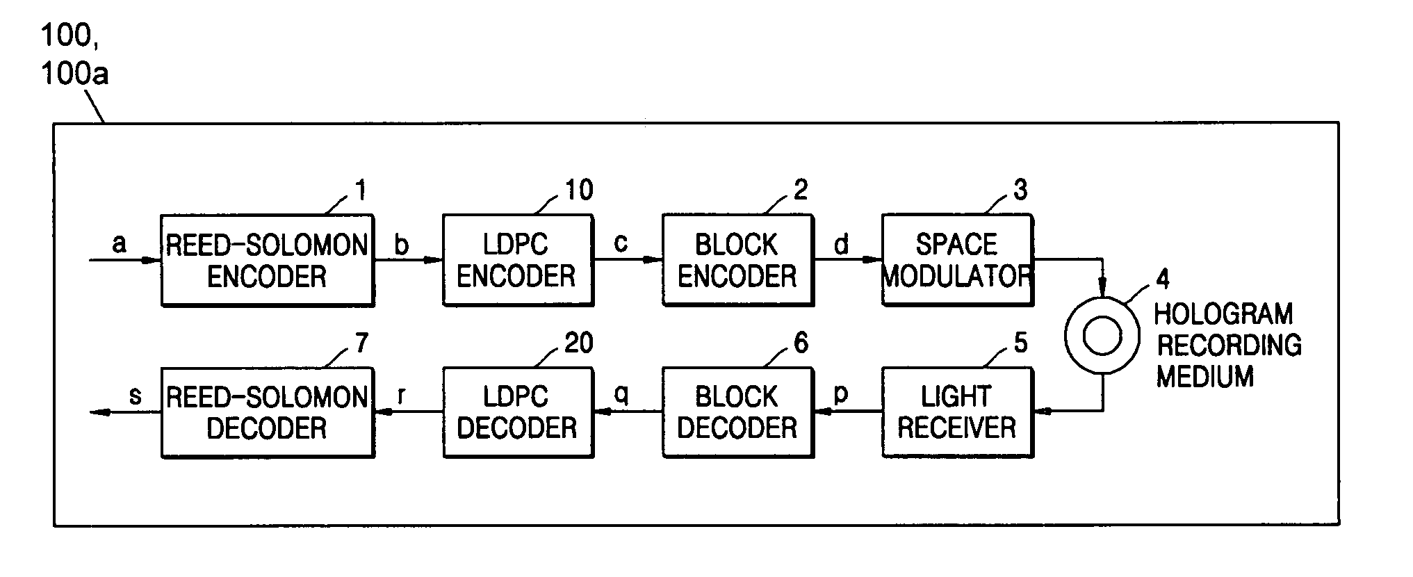
[0044] Referring to FIG. 7, a signal processor of a hologram recording and reproducing apparatus 100 and a hologram reproducing apparatus 100a according to a first embodiment of the present invention includes, a Reed-Solomon encoder 1, a low-density parity check (LDPC) encoder 10, a block encoder 2, a space modulator 3, a light receiver 5, a block decoder 6, an LDPC decoder 20, and a Reed-Solomon decoder 7.

[0045] The Reed-Solomon encoder 1 encodes recording data a using a Reed-Solomon code and generates a recording Reed-Solomon code b. The LDPC encoder 10 encodes the recording Reed-Solomon code b using an LDPC code and generates a recording LDPC code c.

[0046] The block encoder 2 encodes the recording LDPC code c using a block code and generates a recording block code d. The space modulator 3 transmits or intercepts object beams of respective pixels, and generates recording-page data having a checkered pattern corresponding to the recording block code d. A hologram recording medium...

second embodiment

[0065] Although a differential code is used as the block code in the first embodiment, a 2:4 code may also be used. An encoding rule of the 2:4 code is illustrated in FIG. 9 and an example of the recording-page data is illustrated in FIG. 10.

[0066] In this case, the block decoder 6 compares the brightness levels of four pixels constituting code words of the 2:4 code and sets levels of the pixels to P1, P2, P3, and p4 in order of increasing brightness. The level difference Δ may be given by, for example, equation 28, equation 29 or equation 30. Δ=p1-(p2+p3+p4)(28)Δ=p1-p1+p2+p3+p44(29)Δ=p1-p2(30)

[0067] Referring to FIG. 9, when the brightness level of the right-upper pixel is highest, the reproducing block code {circumflex over (d)}, which is an estimated value of the recording block code d, is given by equation 31 and the reproducing LDPC code ĉ, which is an estimated value of the recording LDPC code c, is given by equation 32. d^=[0100](31)c^=[01](32)

[0068] Since the estimated re...

third embodiment

[0070] A code (hereinafter, referred to as a 5:9 code) in which two of nine pixels are “1” and the other seven pixels are “0” may be employed as the block code. An example of the encoding rule of the 5:9 code is partially illustrated in FIG. 11.

[0071] In this case, the block decoder 5 selects two of the nine pixels constituting a code word of the 5:9 code in order of increasing brightness, and it is assumed that the levels of the two selected pixels are p1 and P2 and that the levels of the other seven pixels are p3, p4, P5, P6, P7, P8, and p9. The level difference Δ may be given by any one of equation 34, equation 35, or equation 36. Since 8 may be expressed as 23, that is, a power of 2, the number 8 is set as a denominator of the second term in the right side of equation 35 and equation 36 for easy division in a digital circuit. When the reproducing signal p passes through a high-pass filter, the second term in the right side of equation 36 is almost 0 and is removed, and thus the...


PUM

PropertyMeasurementUnit
densityaaaaaaaaaa
brightnessaaaaaaaaaa
signal-to-aaaaaaaaaa

Abstract

A hologram recording and reproducing apparatus having a reduced encoding error and high reliability even when a signal-to-noise (S / N) ratio of reproducing signals is deteriorated due to various disturbances. The hologram recording and reproducing apparatus includes: a unit generating a recording low-density parity check code from recording data; a unit generating a recording block code from the recording low-density parity check code; a unit recording data by emitting an object beam onto a hologram recording medium; a unit reproducing data by emitting a reference beam onto the hologram recording medium; a unit decoding a reproducing block code corresponding to the recording block code based on the levels of a reproducing signal, decoding a reproducing low-density parity check code corresponding to the recording low-density parity check code based on the reproducing block code, and calculating estimation data estimating values of respective bits of the reproducing low-density parity check code based on the level of the level of the reproducing signals; and a unit decoding the low-density parity check code based on the estimation data and decoding the recording data.

Description

CROSS-REFERENCE TO RELATED APPLICATIONS [0001] This application claims the benefit of Japanese Patent Application No. 2004-112363, filed Apr. 6, 2004 in the Japanese Intellectual Property Office, the priority of Korean Patent Application No. 2004-80734, filed Oct. 9, 2004 in the Korean Intellectual Property Office, the disclosures of which are incorporated herein in their entirety by reference. BACKGROUND OF THE INVENTION [0002] 1. Field of the Invention [0003] The present invention relates to a hologram recording and reproducing apparatus and a hologram reproducing apparatus to record data to a hologram medium and to reproduce the recorded data, and, more particularly, to a hologram recording and reproducing apparatus and a hologram reproducing apparatus which reduce a decoding error even when a signal-to-noise (S / N) ratio of a reproduced signal deteriorates due to disturbances. [0004] 2. Description of the Related Art [0005] Recently, rewritable optical disks such as phase-change ...

Claims


Application Information

Patent Timeline
Patent Type & Authority Applications(United States)
IPC IPC(8): G06F11/00G11B20/10G11B20/18H03M13/00
CPCG11B7/0065G11B20/10G11B2020/185G11B2020/1836G11B20/1833
Inventor HAYASHI, HIDEKI
Owner SAMSUNG ELECTRONICS CO LTD
Why Eureka
Try Eureka