Communication method in RFID or remote sensor systems

a communication method and sensor technology, applied in the direction of burglar alarm mechanical actuation, burglar alarm by hand-portable objects removal, instruments, etc., can solve the problems of affecting the reception of the control unit, affecting the reliability of the transponder, and affecting the accuracy of the transponder

Inactive Publication Date: 2005-11-03
ATMEL CORP
View PDF10 Cites 28 Cited by
  • Summary
  • Abstract
  • Description
  • Claims
  • Application Information

AI Technical Summary

Benefits of technology

[0033] Thus, according to the invention, the acknowledgment symbol for the reliability data or, respectively, the end symbol simultaneously can serve as an acknowledge symbol, thereby eliminating transmission of an additional acknowledge symbol that is generally provided in prior art methods for confirming large data transfers, in particular.
[0034] In order to then be able to continue quickly with a new time window for the purpose of streamlining the timing of the process, an advantageous further development of the invention is characterized in that, in the event of the first two alternatives listed above, the control unit subsequently trans...

Problems solved by technology

Hence an information query from the control unit can under certain circumstances result in a plurality of (simultaneous) transmissions from remote units to the control unit (known as multiple access), which generally disrupts or at least impedes reception by the control unit, especially when the remote units transmit with only very low useful signal strength, such as is the case with backscatter-based RFID systems.
Another fundamental problem in the aforementioned communication systems is associated with the time period that must be calculated for reading information with a plurality of remote units, wherein efforts are frequently made to minimize the length of this time period.
It must be viewed as a particular disadvantage here that an ASK-based backscatter transponder in particular must disable its RSSI channel (RSSI=receiver signal strength indicator) when operating its ASK modulator on account of overshoot problems caused by the occurrence of peaks during ASK modulation.
Moreover it is necessary, especially with large transmission distances, to operate with a large modulation index m close t...

Method used


Image

  • Communication method in RFID or remote sensor systems
  • Communication method in RFID or remote sensor systems
  • Communication method in RFID or remote sensor systems

Examples


Embodiment Construction

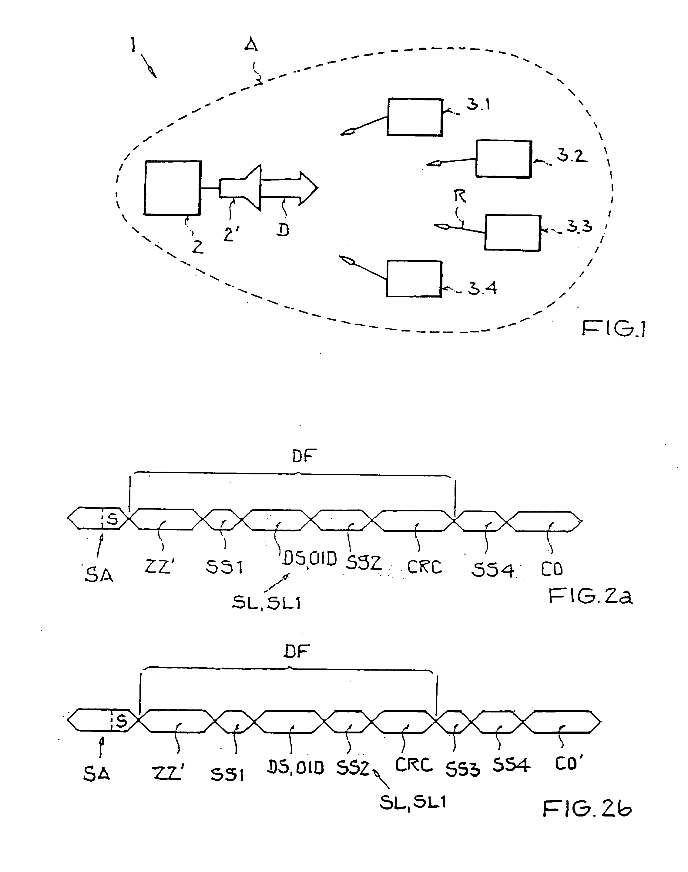
[0046]FIG. 1 shows an RFID system 1 with a control unit in the form of a reader 2 (base station) in connection with suitable transmitting and receiving means 2′, such as a dipole antenna, and a number of remote units (transponders 3.1-3.4), which are all located in a response area A of the reader 2.

[0047] In this situation, a data stream D transmitted by the reader 2 or the transmitting means 2′ is received simultaneously by all transponders 3.1-3.4. The data transmission from the reader 2 to a transponder 3.1-3.4 is referred to below as forward link. The transponders 3.1-3.4 reply at least to a completed data transmission from the reader 2 through return links R, wherein a part of the energy received together with the data D at the transponder 3.1-3.4 is reflected (backscattered) and may be modulated for data transmission from the transponders 3.1-3.4 to the reader 2. When full-duplex-capable systems 1 are used in accordance with a preferred first embodiment of the inventive metho...


PUM


Abstract

A method for communicating between a control unit and a plurality of remote units located in the response area of the control unit is provided. The remote units are prompted to transmit a data sequence to the control unit upon receipt of a command sent by the control unit. The control unit transmits a control signal to the remote units substantially simultaneously with the transmission of the data sequence as a function of a communication state, such as the absence of a transmission of the data sequence by at least one remote unit or an at least partially simultaneous transmission of the data sequence by more than one remote unit. In this way, communication methods can be shortened, in particular in terms of time, without adversely affecting communication reliability.

Description

[0001] This nonprovisional application claims priority under 35 U.S.C. § 119(a) on German Patent Application No. DE 102004020956.1, which was filed in Germany on Apr. 28, 2004, and which is herein incorporated by reference. BACKGROUND OF THE INVENTION [0002] 1. Field of the Invention [0003] The present invention relates to a method for communicating between a control unit and a number of remote units located in the response area of the control unit, for example, a base station and a number of tags in RFID or remote sensor systems, wherein the remote units are prompted to transmit a data sequence to the control unit in executing a command sent by the control unit. [0004] 2. Description of the Background Art [0005] Today a wide variety of technical applications are known which use communication systems having at least one control unit or base station and a plurality of remote units arranged in a communication field about the control unit. In this context, the control unit is frequentl...

Claims


Application Information

Patent Timeline
IPC IPC(8): G06K7/00H04B7/212H04Q5/22
CPCG06K7/10019G06K7/0008
Inventor FRIEDRICH, ULRICH
Owner ATMEL CORP
Why Eureka
Try Eureka