
Scanning apparatus using vibration light modulator

Inactive Publication Date: 2005-11-03
SAMSUNG ELECTRO MECHANICS CO LTD
View PDF10 Cites 0 Cited by
  • Summary
  • Abstract
  • Description
  • Claims
  • Application Information

AI Technical Summary

Benefits of technology

[0017] Accordingly, the present invention has been made keeping in mind the above problems occurring in the prior art, and an object of the present invention is to provide a scanning apparatus, which

Problems solved by technology

In such a scheme, high speed and high quality characteristics can be realized, but the cost increases due to the use of a plurality of light sources.
In the laser scanning scheme, it is difficult to attain a high printing speed due to problems related to the low switching speed of the laser diode 10 and the scanning speed of the polygon mirror 40.
However, the higher speed motor is expensive, and the motor rotating at high speed causes heat, vibration and noise to incur problems such as the deterioration of operating reliability, so that a great improvement in scanning speed cannot be expected.
However, if a plurality of LEDs is used so as to construct the LED array 80, the cost increases, and light uniformity between LEDs in the array is decreased, so that it is difficult to obtain uniform images.
However, the “scanning apparatus using a piezoelectric / electrostrictive diffractive vibration light modulator”, according to the prior improved technology is problematic in that, although it generates a plurality of diffracted beams using a single beam to enable high speed scanning, the number of actuating cells required for the diffractive light modulator to provide pixels required by the scanning apparatus is very large, so that it is difficult to manufacture and control the scanning apparatus, and the cost is increased.

Method used


Image

  • Scanning apparatus using vibration light modulator
  • Scanning apparatus using vibration light modulator
  • Scanning apparatus using vibration light modulator

Examples


Embodiment Construction

[0037] Hereinafter, the construction of a scanning apparatus using a diffractive light modulator according to embodiments of the present invention will be described in detail with reference to the attached drawings. In the embodiments of the present invention, a piezoelectric / electrostrictive diffractive light modulator is described as an example of a diffractive light modulator, but the present invention can also be applied to transmissive, reflective and other diffractive light modulators.

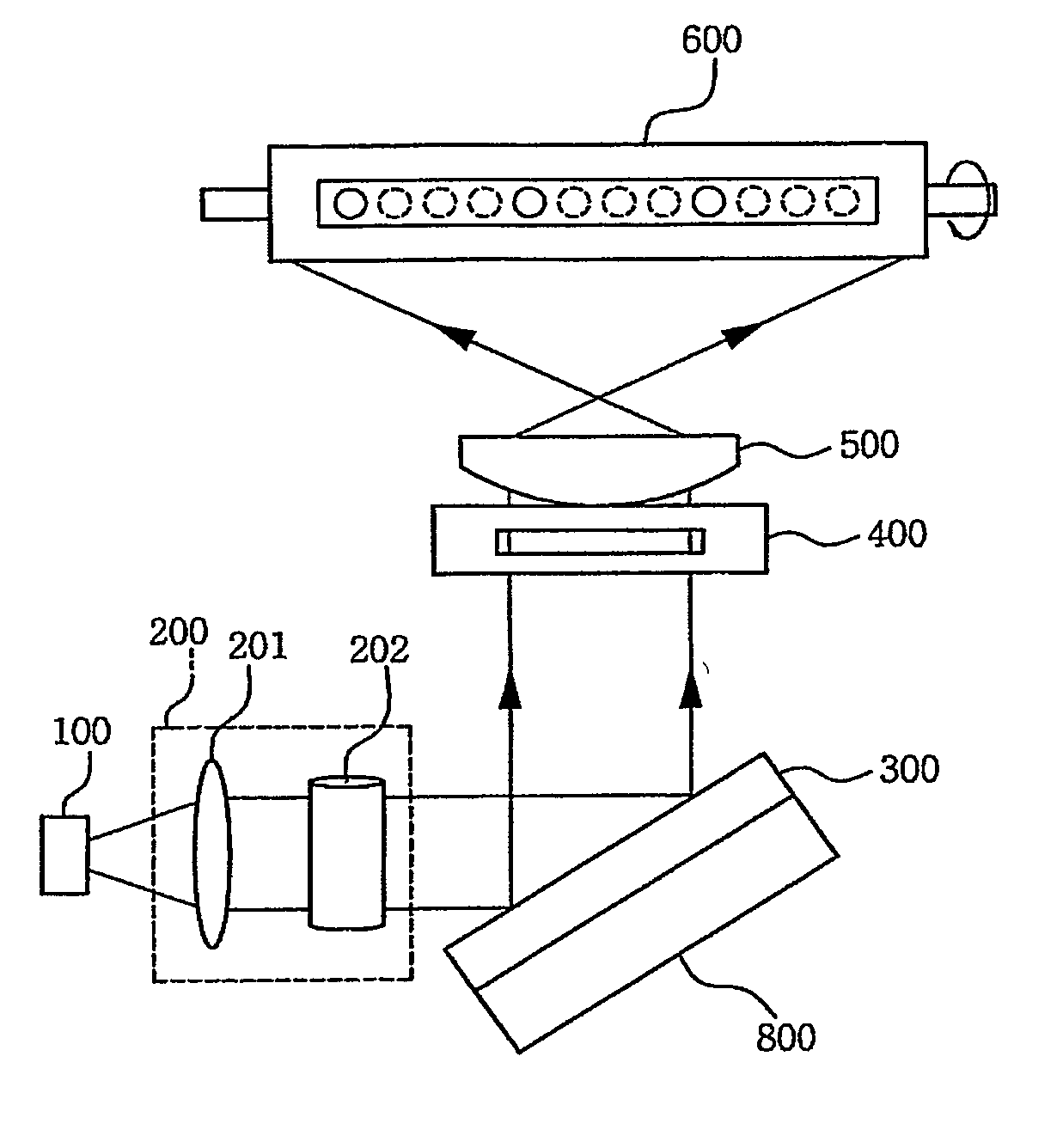
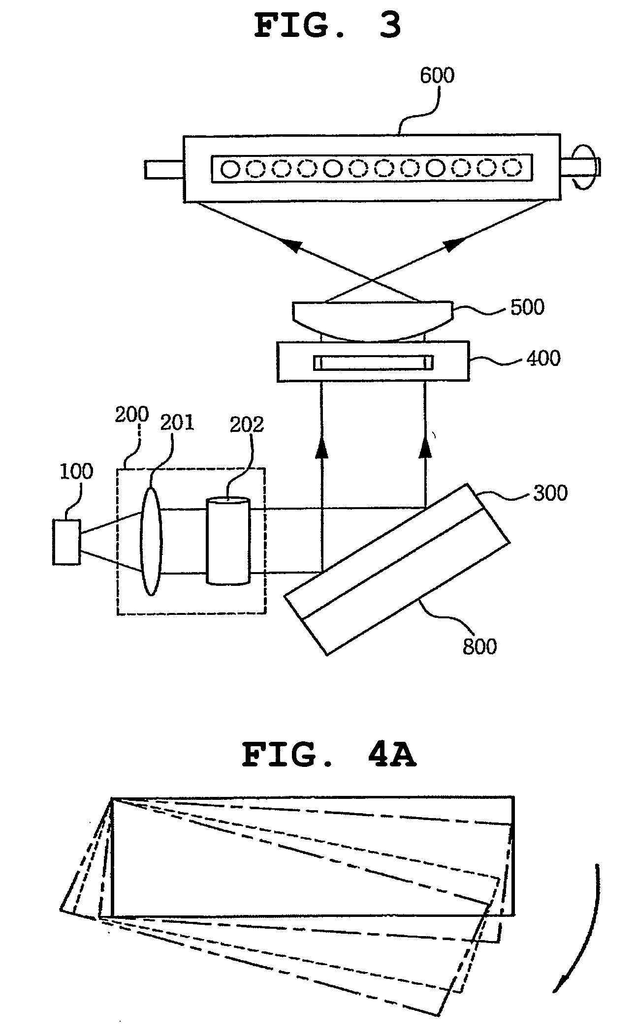
[0038] First, with reference to FIGS. 3, 4a and 4b, the construction of a scanning apparatus using a diffractive vibration light modulator according to the present invention is described in detail.

[0039] The scanning apparatus using a diffractive vibration light modulator according to the present invention performs high speed scanning using a plurality of beams formed by diffraction occurring at a piezoelectric / electrostrictive diffractive light modulator, which performs a piezoelectric / electro...


PUM


Abstract

The present invention relates, in general, to scanning apparatuses using a vibration light modulator and, more particularly, to a scanning apparatus using a vibration light modulator, which performs high speed scanning using a plurality of diffracted beams, formed from a single beam by the reflection and diffraction thereof, and allows each of diffracted beams to form a plurality of pixels by vibrating actuating cells of the light modulator.

Description

BACKGROUND OF THE INVENTION [0001] 1. Field of the Invention [0002] The present invention relates, in general, to scanning apparatuses using a vibration light modulator and, more particularly, to a scanning apparatus using a vibration light modulator, which performs high speed scanning using a plurality of diffracted beams formed through the light modulator, and allows each of the diffracted beams to form a plurality of pixels by vibrating the light modulator. [0003] 2. Description of the Related Art [0004] Printer technology has been developed toward high speed, miniaturization, high quality and low cost. Typical printers employ a laser scanning scheme of scanning laser beams using a Laser Diode (LD) and an f-θ lens. [0005] In order to realize a high speed printer, an image head scheme using a multibeam type beam generation device is used. In such a scheme, high speed and high quality characteristics can be realized, but the cost increases due to the use of a plurality of light sou...

Claims


Application Information

Patent Timeline
IPC IPC(8): B41J2/47G02B26/00G02B26/10H04N1/12
CPCG02B26/105H04N1/1275H04N1/12G02B26/106G02B26/10G02B26/00
Inventor YUN, SANG KYEONG
Owner SAMSUNG ELECTRO MECHANICS CO LTD
Features
  • Generate Ideas
  • Intellectual Property
  • Life Sciences
  • Materials
  • Tech Scout
  • Unparalleled Data Quality
  • Higher Quality Content
  • 60% Fewer Hallucinations
Learn More