Heat exchanger including flow straightening fins

Active Publication Date: 2005-11-03
HEWLETT-PACKARD ENTERPRISE DEV LP
View PDF21 Cites 29 Cited by
  • Summary
  • Abstract
  • Description
  • Claims
  • Application Information

AI Technical Summary

Benefits of technology

[0003] In accordance with an embodiment of an electronic liquid cooling system, a heat exchanger includes a tube, and a pl

Problems solved by technology

Electronic equipment contained within the enclosure generates a significant amount of

Method used


Image

  • Heat exchanger including flow straightening fins
  • Heat exchanger including flow straightening fins
  • Heat exchanger including flow straightening fins

Examples


Embodiment Construction

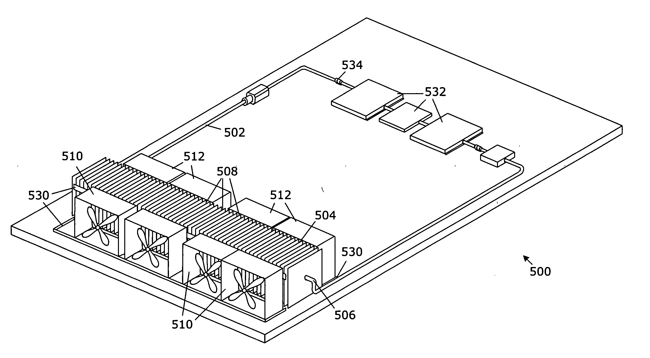
[0014] Compact electronic devices and systems, such as server architectures, may use a liquid loop cooling solution to accommodate increasing power and power density levels for microprocessors and associated electronics. Liquid loops can use a pump to drive cooling fluid through high pressure-drop channels of the colds plates attached to processors and other high-power components and along potentially long and narrow-diameter tube completing the loop between the cold plate, condenser, and pump. Heat is removed from the loop by forced-air convection at the heat exchanger.

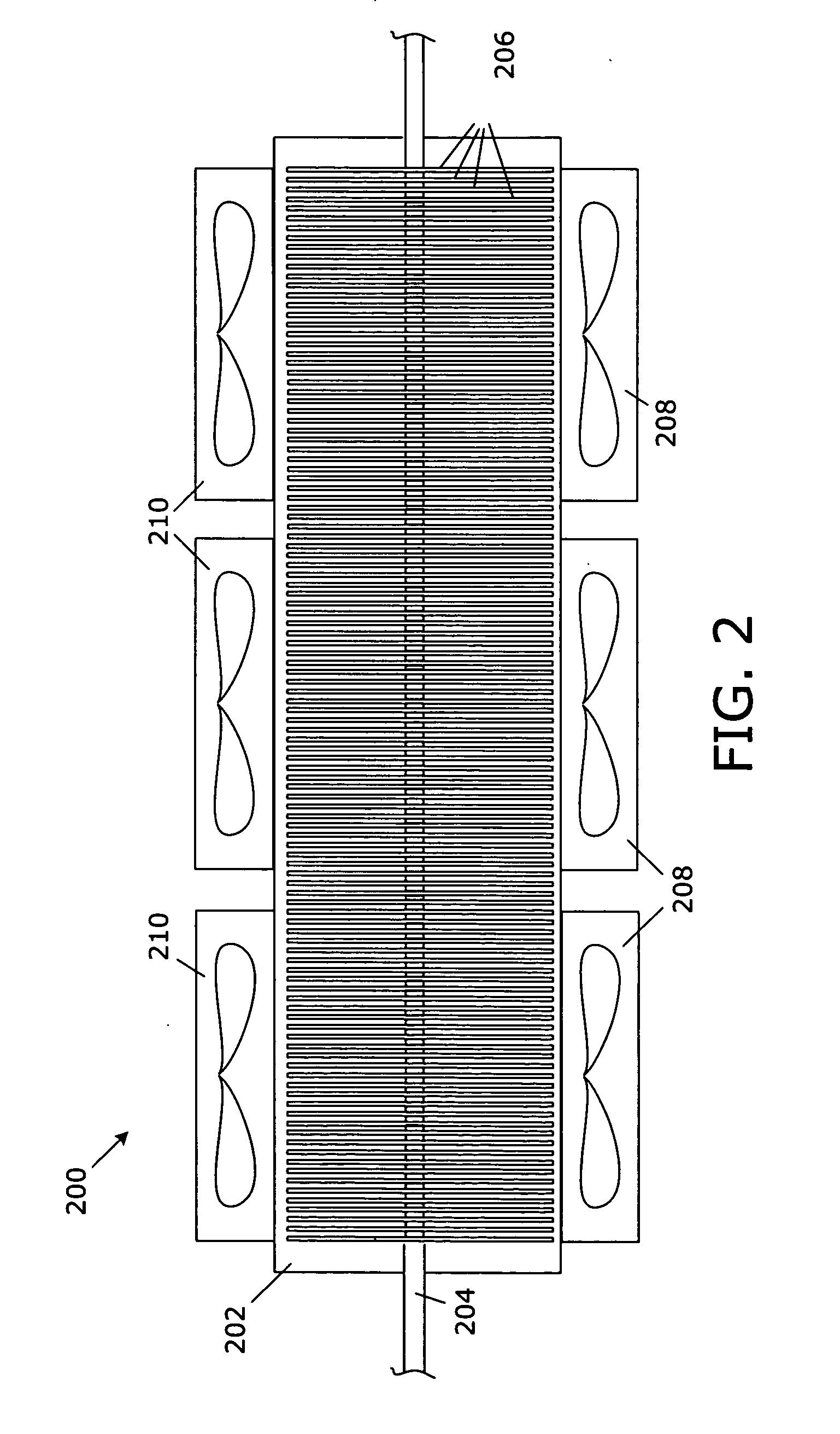
[0015] Various embodiments of a disclosed electronic system and liquid loop cooling system describe a heat exchanger with fins configured to straighten airflow for optimized fan performance. The heat exchanger and fins can further be configured for acoustic noise reduction.

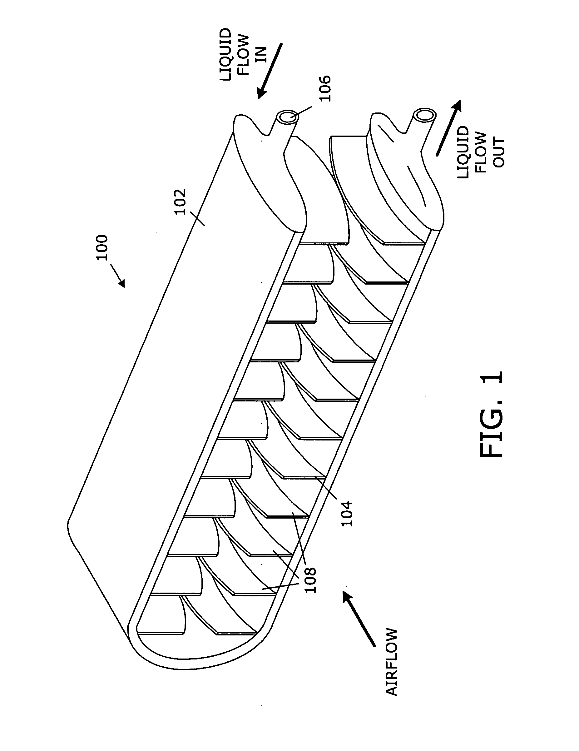
[0016] Referring to FIG. 1, a perspective pictorial drawing illustrates an embodiment of a heat exchanger 100 that includes a tube 102, and a pl...


PUM


Abstract

A heat exchanger includes a tube, and a plurality of fins coupled to the tube having a curved fan-stator shape that facilitates straightening of airflow from a fan.

Description

BACKGROUND OF THE INVENTION [0001] Electronic systems and equipment such as computer systems, network interfaces, storage systems, and telecommunications equipment are commonly enclosed within a chassis, cabinet or housing for support, physical security, and efficient usage of space. Electronic equipment contained within the enclosure generates a significant amount of heat. Thermal damage may occur to the electronic equipment unless the heat is removed. [0002] As electronic components and subsystems evolve to increasing capability, performance, and higher power, while reducing size and form factor, efficient and cost-effective removal of excess heat is desired. Among available thermal management solutions, liquid cooling via cold plate technology offers high capacity for heat rejection and movement of heat from internal sources to external ambient air. Liquid cooling loop systems typically cycle pumped coolants continuously, conveying excess heat from heat-generating devices. The he...

Claims


Application Information

Patent Timeline
IPC IPC(8): F25D9/00F28D1/047F28D11/08F28F1/24F28F1/32F28F13/06G06F1/20H05K7/20
CPCF28D1/0478F28D2021/0031H05K7/20009F28F13/06G06F1/20F28F1/24
Inventor MALONE, CHRISTOPHER G.SIMON, GLENN C.
Owner HEWLETT-PACKARD ENTERPRISE DEV LP
Why Eureka
Try Eureka