Optical transmission system, optical transmission and reception apparatus, optical transmission apparatus, optical wavelength channel connection recognition control method and wavelength allocation apparatus

Inactive Publication Date: 2005-11-03
FUJITSU LTD
View PDF8 Cites 24 Cited by
  • Summary
  • Abstract
  • Description
  • Claims
  • Application Information

AI Technical Summary

Benefits of technology

[0025] It is an object of the present invention to provide an optical transmission system, an optical transmission and reception apparatus, an optical transmission apparatus, an optical wavelength channel connection recognition control method and a wavelength allocation apparatus wherein procedures for wavelength detection, wavelength setting and wavelength selection for a plurality of monochromatic-wavelength lights in a WDM transmission system included in an optical transmission system are automated to significantly improve the convenience in channel allocation thereby to achieve simplicity and improvement in efficiency of a cross connection function and reduction of the cost.
[0033] Consequently, for example, a wavelength setting and connection correct / wrong (connection allowance / rejection) discrimination can be performed simultaneously and efficiently.
[0039] Consequently, since automatic wavelength setting is permitted after connection of an optical fiber, control, supervision and maintenance can be performed simply and conveniently and the facility can be improved significantly. Consequently, construction of an optical transmission system can be promoted.
[0041] With this, wavelength setting and connection correct / wrong or connection allowance / rejection discrimination can be performed simultaneously and efficiently based on the sweep control.
[0045] Consequently, a plurality of wavelengths can be automatically set at a time, and rapid and efficient wavelength setting can be achieved. Further, in a wavelength division multiplexing optical transmission apparatus, for example, when a transmission port is changed or a wavelength allocated to a transmission port is changed, a wavelength can be re-set. Furthermore, a re-configuration function for transmitting a designated wavelength from the optical transmission and reception apparatus and a detection function of an improper connection can be implemented.
[0052] Accordingly, for example, a reduction in cost for newly development is achieved, and the existing processing module for signal light can be available.

Problems solved by technology

Consequently, many and unspecified users can freely perform multicast communication.
However, reviewing upon each of above methods (i)-(iv), the cross connect apparatus of item (i) and the add / drop apparatus of item (iv) are both very expensive, and where a case wherein the number of channels is small, or the number of channels or the arrangement of channels changes after operation of the system is started, is taken into consideration, in most cases the suitable cross connect apparatus etc. cannot be provided.
Particularly where the cross connect function of item (iv) is provided in the WDM transmission system, the cost required for implementation of some hundreds of×some hundreds of cross connects for individually some hundreds of monochromatic-wavelength lights being currently used (in service) is extremely expensive and not realistic at all.
On the other hand, where the OEO conversion of item (ii) is used, expansion or reduction of the system cannot sometimes be performed appropriately.
The OEO conversion of item (iii) has another subject to be solved in that, due to the complicatedness in connection and wavelength setting of optical fibers by manual operation, there is the possibility that an error in connection or in setting of a wavelength may occur and besides an increased cost is required for construction and for maintenance and management of the system.

Method used


Image

  • Optical transmission system, optical transmission and reception apparatus, optical transmission apparatus, optical wavelength channel connection recognition control method and wavelength allocation apparatus
  • Optical transmission system, optical transmission and reception apparatus, optical transmission apparatus, optical wavelength channel connection recognition control method and wavelength allocation apparatus
  • Optical transmission system, optical transmission and reception apparatus, optical transmission apparatus, optical wavelength channel connection recognition control method and wavelength allocation apparatus

Examples


first embodiment

[0081] (A) Description of the Present Invention

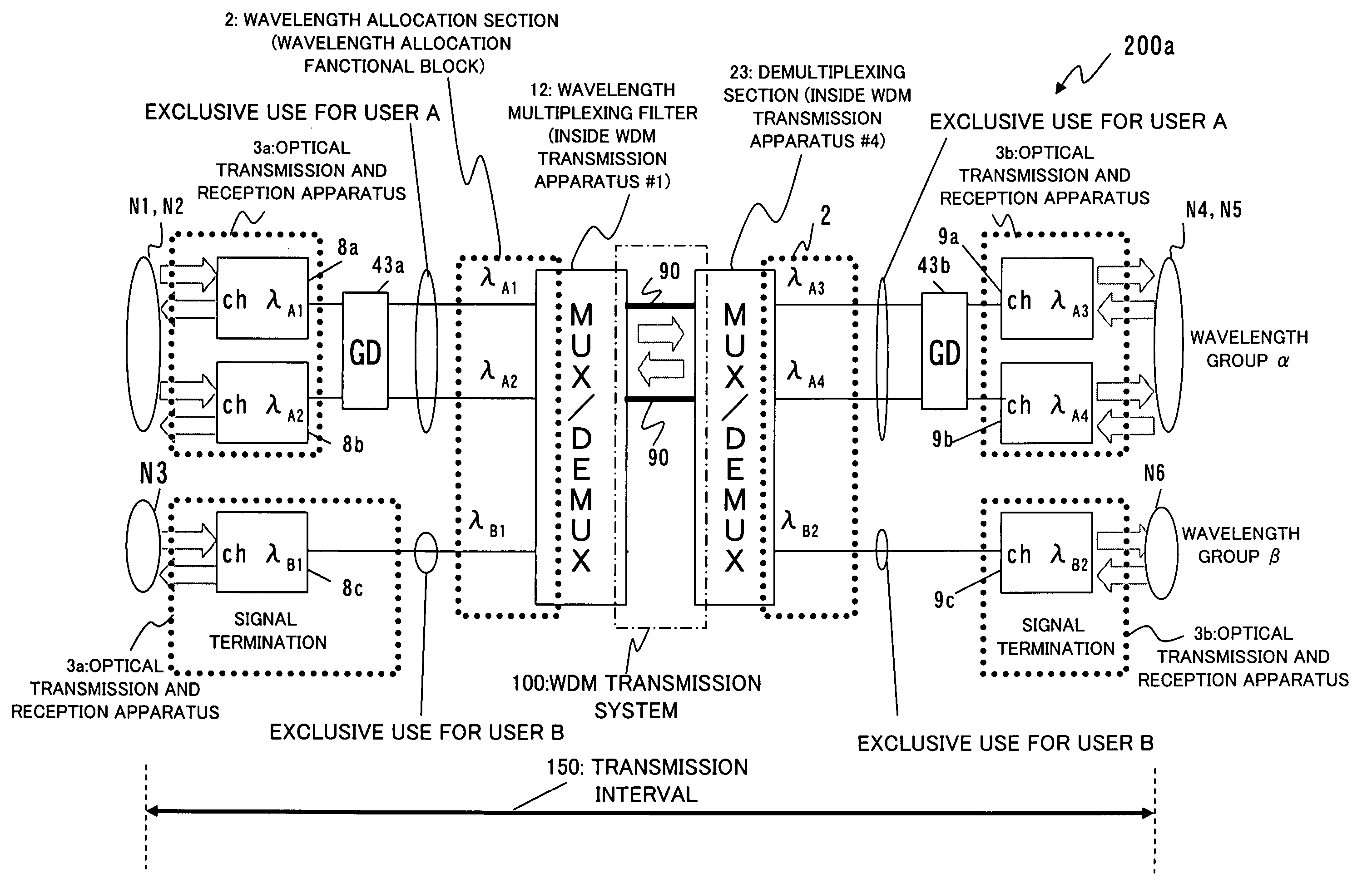
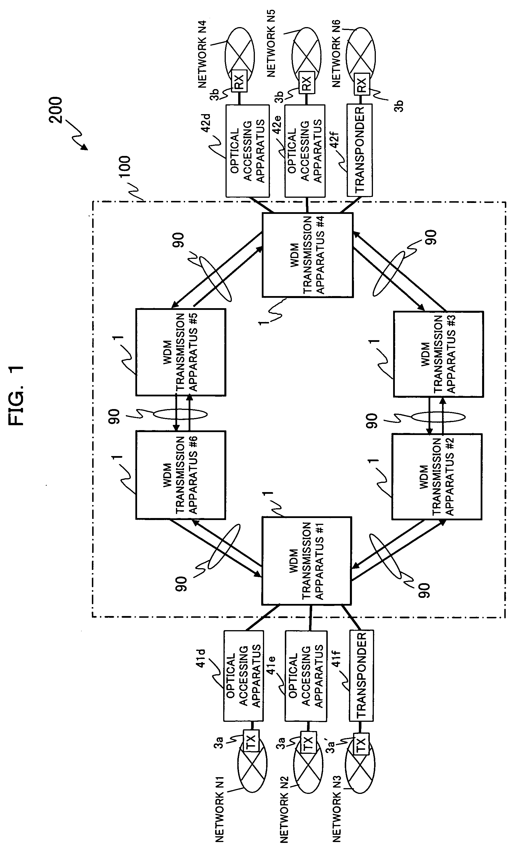
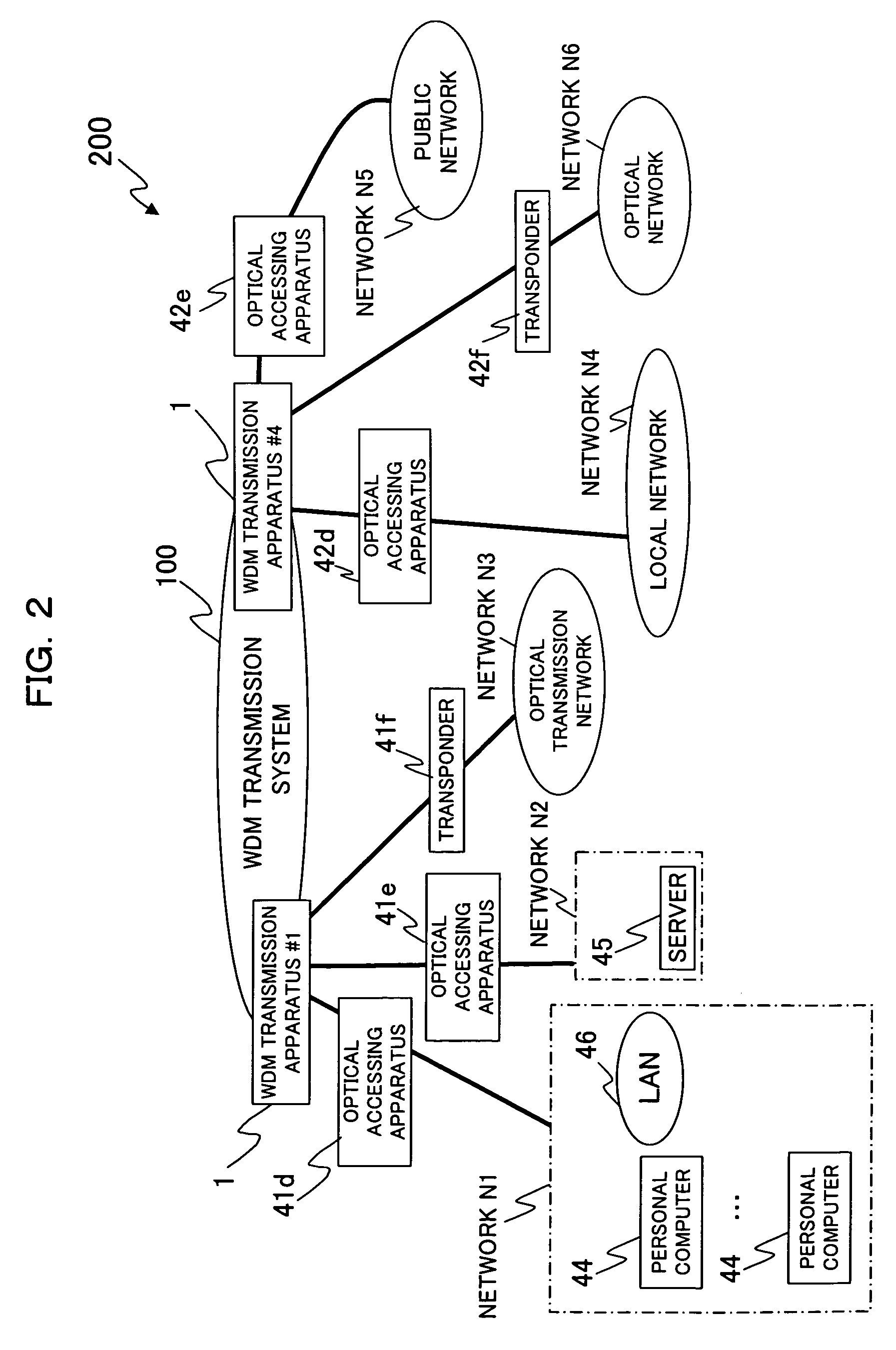
[0082]FIG. 1 is a diagrammatic view showing an example of a configuration of an optical transmission system (optical transmission network system) to which the present invention is applied. Referring to FIG. 1, the optical transmission system 200 shown performs multiplexing and transmitting a plurality of monochromatic lights having wavelengths different from each other. The optical transmission system 200 performs a wavelength division multiplexing process for signal lights, which is obtained by EO converting broadband data packets of moving picture image data or the like into any of the plurality of monochromatic-wavelength lights or obtained by converting lights having a low-transmission speed or electric signals, through bundling and high-speeding, into the monochromatic lights (single-wavelength lights), and performs a WDM transmission process for thus obtained multiplexed signal lights. Then, the optical transmission system 200 wav...

second embodiment

[0222] Further, the automatic setting represents a setting collectively a plurality of wavelengths of signal light outputted from the optical transmission and reception apparatus 3a for each of user A, B. Note the automatic re-setting is described later in the

[0223] With this, a manager would insert (or connect) two optical fibers 90 connected to two ones of the transmission ports (for example, a pair of neighborhood transmission ports) 21a of the optical transmission and reception apparatus 3a into the reception ports 22b, respectively. The WDM transmission apparatus #1, when detects a insertion (or connection) of the optical fiber 90 to reception ports 22b regarding use A, superposes a control request to the main signal light and transmits the superposed main signal light to the optical transmission and reception apparatus 3a.

[0224] The photodiode 25 of the WDM transmission apparatus #1 monitors and detects an optical signal power inputted from the reception ports 22b, and notifi...

first modification

[0311] (9-1) First Modification

[0312] Referring to above, for example, FIG. 8, the functions for transmission of the a monochromatic-wavelength lights, control and so forth are provided in the optical transmission and reception apparatus 3a while the functions for wavelength allocation, notification and so forth are provided in the WDM transmission apparatus #1, and these functions are provided scatteringly. Accordingly, the functions mentioned can be provided separately from the optical transmission and reception apparatus 3a and the WDM transmission apparatus #1.

[0313] Concretely, a modified configuration is realized by eliminating each port (such as the transmission port 21a, the reception port 22a both provided in the optical transmission, and the reception ports 22b, 21b both provided in the WDM transmission apparatus #1) and the optical fiber 90 connected to these ports, respectively, and concentrating above each function.

[0314] Then, the optical transmission system 200 chan...


PUM


Abstract

The present invention relates to an optical wavelength channel connection recognition control method. In an optical transmission system, a transmission section outputs plural monochromatic-wavelength lights individually, a first allocation section allocates a wavelength of a monochromatic-wavelength light based on a power of the monochromatic-wavelength light individually outputted from the transmission section from among the plural monochromatic-wavelength lights, a notification section issues a notification of wavelength information of the monochromatic-wavelength lights allocated by the first allocation section to the transmission section, and a first control section controls wavelengths of the monochromatic-wavelength lights to be outputted from the transmission section based on the wavelength information of the notification issued from the notification section. With this configuration, the optical transmission system becomes automated to significantly improve a convenience in channel allocation thereby to achieve simplification and improvement in efficiency of a cross connection function and reduction of a cost.

Description

BACKGROUND OF THE INVENTION [0001] (1) Field of the Invention [0002] The present invention relates typically to an optical transmission network apparatus, and more particularly to an optical transmission system, an optical transmission and reception apparatus, an optical transmission apparatus, an optical wavelength channel connection recognition control method and a wavelength allocation apparatus which can perform an automatic wavelength setting process, a control process and a cross-connection process for each of a plurality of wavelength channels (optical wavelength channels), suitable for use with a WDM (Wavelength Division Multiplexing) transmission system (hereinafter referred to simply as WDM transmission system). [0003] (2) Description of Related Art [0004] Generally, a WDM transmission system is used as a network for provision of a distribution service for distributing broadband data such as moving picture image data to a great number of network apparatus (network nodes) a...

Claims


Application Information

Patent Timeline
IPC IPC(8): H04B10/07H04J14/00H04B10/27H04B10/275H04J14/02
CPCH04J14/0221H04J14/0227H04J14/025H04J14/0246H04J14/0283
Inventor SATOH, REIKO
Owner FUJITSU LTD
Why Eureka
Try Eureka