Vehicle suspension system

Inactive Publication Date: 2005-11-03
KILBURN KIP K +1
View PDF20 Cites 1 Cited by
  • Summary
  • Abstract
  • Description
  • Claims
  • Application Information

AI Technical Summary

Benefits of technology

[0008] When the conventional upper and lower ball joints or tie rod ends are replaced with the Hime Joint and the newly invented tapered or straight insert is installed, new and unexpected results occur. The Hime Joint, when fitted with the newly invented tapered or straight insert provides proportionally greater vertical and or horizontal travel. This extra travel results in a dramatically improved suspension system; one that is up to eighty percent stronger and weighs less than the conventional ball joint system. Additionally the unsprung weight of the suspension system is reduced and handling is vastly improved. Friction is also greatly reduced compared to the conventional style ball joint.

Problems solved by technology

While it does offer the rotational capability of the ball joint, it lacks the connecting insert to allow it to act as a ball joint or tie rod end.

Method used


Image

  • Vehicle suspension system
  • Vehicle suspension system
  • Vehicle suspension system

Examples


Embodiment Construction

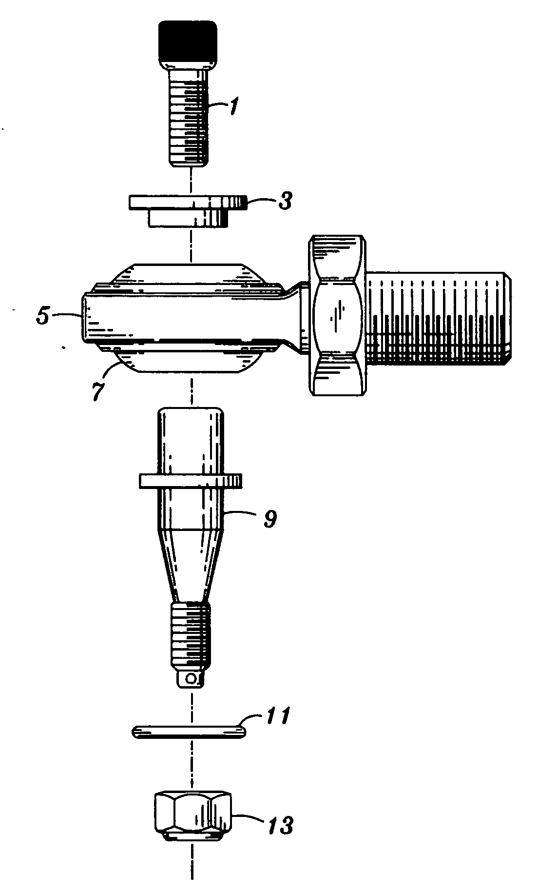
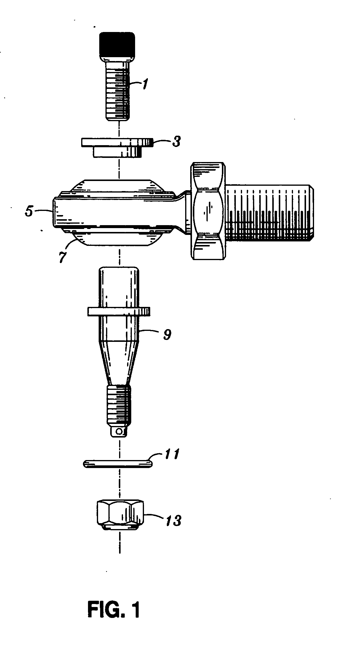
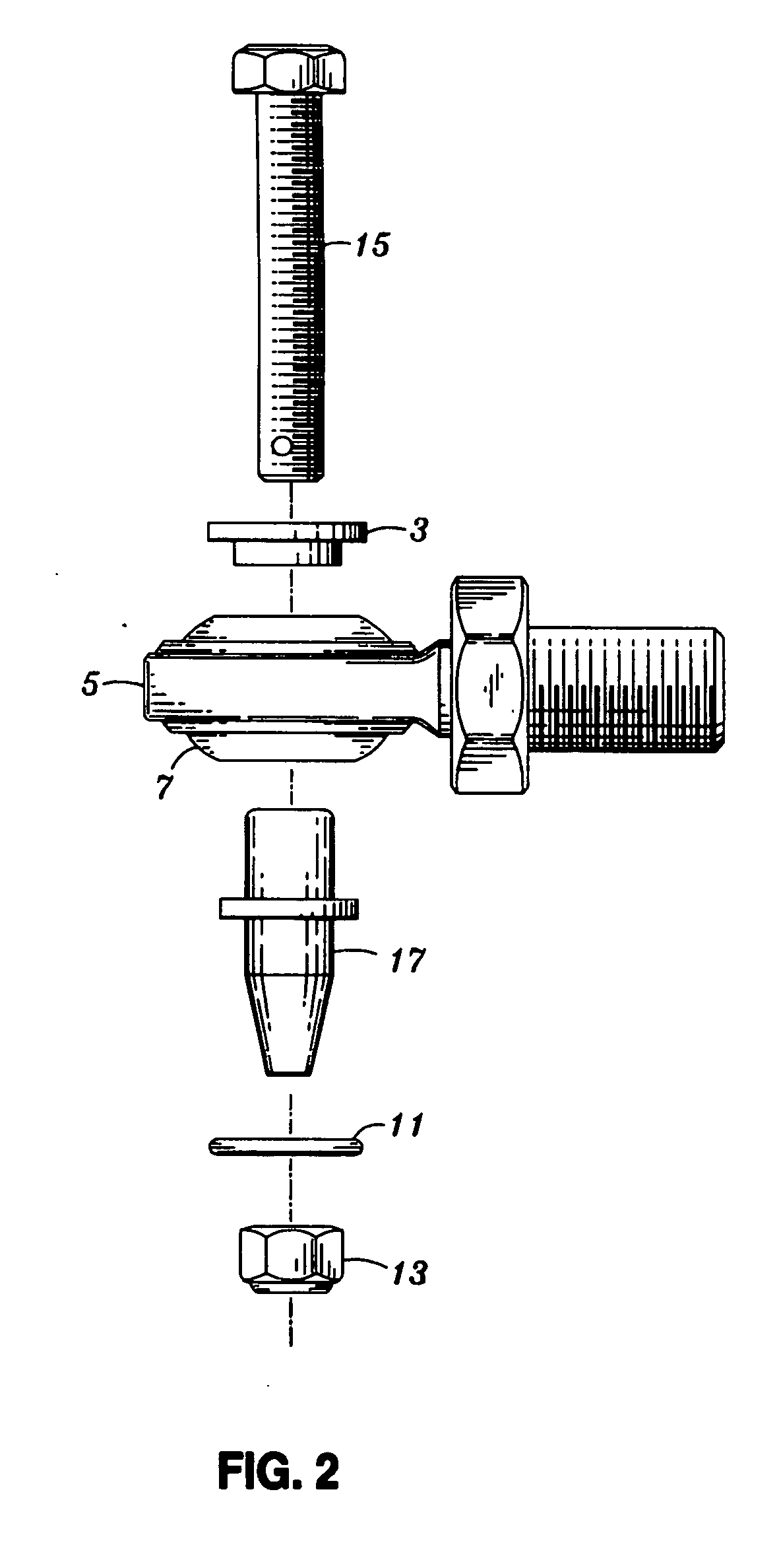
[0011] The Hime Joint comprises an annular shaped socket. The socket encases a freely movable ball shaped member with an included opening in the center. The presently preferred embodiment is a two piece (upper and lower) tapered or straight insert, which is mounted and secured within the included opening of the freely movable ball shaped member of the Hime Joint. This embodiment is attached to the ball shaped member by either a bolt securing the upper and lower portions together (see FIG. 1) or a bolt passed entirely through the embodiment which is secured by a nut on the bottom (see FIG. 2). The presently preferred embodiment is the stronger and more preferable of the two although both achieve the same end result.

[0012] The normal vehicle suspension system comprises an upper and lower suspension arm, an upper and lower ball joint and a steering knuckle. Additionally it includes tie rods to which tie rod ends are attached. These tie rod ends are attached to a steering stem or steer...


PUM


Abstract

An improved vehicle suspension system in which the conventional upper and lower ball joints, each having a spindle, are replaced by a Hime joint which includes a tapered or straight insert that is dimensioned to accommodate the spindle to which it is attached. The resulting suspension system has enhanced vertical and horizontal travel.

Description

[0001] This is a Continuation-In-Part of application Ser. No. 10 / 614,250 filed Jul. 8, 2003 Applicants claim benefits under 35 U.S.C 119(e) of Provisional Application No. 60 / 393946 filed Jul. 8 2002.BACKGROUND OF THE INVENTION [0002] 1) Field of the Invention [0003] This invention relates generally to the suspension mechanisms of multi-wheeled vehicles such as automotive and all terrain vehicle applications. Additionally it can also be used on snowmobile, watercraft, aircraft and motorcycle applications. Specifically, this invention, when inserted into a Hime Joint as compared to a conventional ball joint permits greater travel in the system while dramatically increasing strength and reducing both weight and replacement cost. Because various tapers are available for specific applications, no modification is required to the spindle or knuckle to which it is attached, unlike similar devices. [0004] 2) Description of the Prior Art [0005] U.S. Pat. Nos. 5,967,580, 5,845,540, and 4,911,0...

Claims


Application Information

Patent Timeline
IPC IPC(8): B60G7/00F16D1/12
CPCY10T403/32631B60G7/005
Inventor KILBURN, KIP K.WINIGER, ROGER ALLEN
Owner KILBURN KIP K
Why Eureka
Try Eureka