Variable displacement compressor

a compressor and variable displacement technology, applied in the direction of machines/engines, positive displacement liquid engines, mechanical equipment, etc., can solve the problems of suction reed valve not opening to a sufficient degree, suction pulsation, performance degradation, etc., and achieve the effect of suppressing the throttle

Active Publication Date: 2005-11-03
TOYOTA IND CORP
View PDF7 Cites 20 Cited by
  • Summary
  • Abstract
  • Description
  • Claims
  • Application Information

AI Technical Summary

Benefits of technology

[0007] The present invention has been made with a view toward solving the above problem in the prior art. It is an object of the present invention to provide a variable displacement compressor which can reliably achieve a reduction in vibration due to suction pressure fluctuation during variable displacement operation and which can secure a sufficient flow rate during maximum displacement operation, thus making it possible to secure the requisite performance.
[0009] By exerting not only the suction pressure but also the crank chamber pressure, which varies according to the displacement, on the opening control valve, it is possible to suppress the throttle effect during maximum displacement operation and to exert the throttle effect to a sufficient degree during small displacement operation.

Problems solved by technology

Thus, when the stopper provided is adjusted to the maximum displacement state, the suction reed valve does not open to a sufficient degree and does not abut the stopper when, in particular, the displacement is small, or when the compressor is started in the OFF state, in which the displacement is minimum.
As a result, the suction reed valve generates self-excited vibration to cause suction pulsation, the vibration of which may be propagated to the exterior of the compressor to thereby generate noise.
However, in the above construction disclosed in U.S. Pat. No. 6,257,848, the opening control valve is operated by utilizing a pressure difference due to the gas flow in the suction passage and a spring force, so that when priority is given to the throttle effect, a throttle effect is also obtained when the displacement is maximum to thereby cause a deterioration in performance, whereas an attempt to secure the performance corresponding to the maximum displacement makes it impossible to effect throttling to a sufficient degree during small displacement operation, which requires a throttle effect.

Method used


Image

  • Variable displacement compressor
  • Variable displacement compressor
  • Variable displacement compressor

Examples


embodiment 1

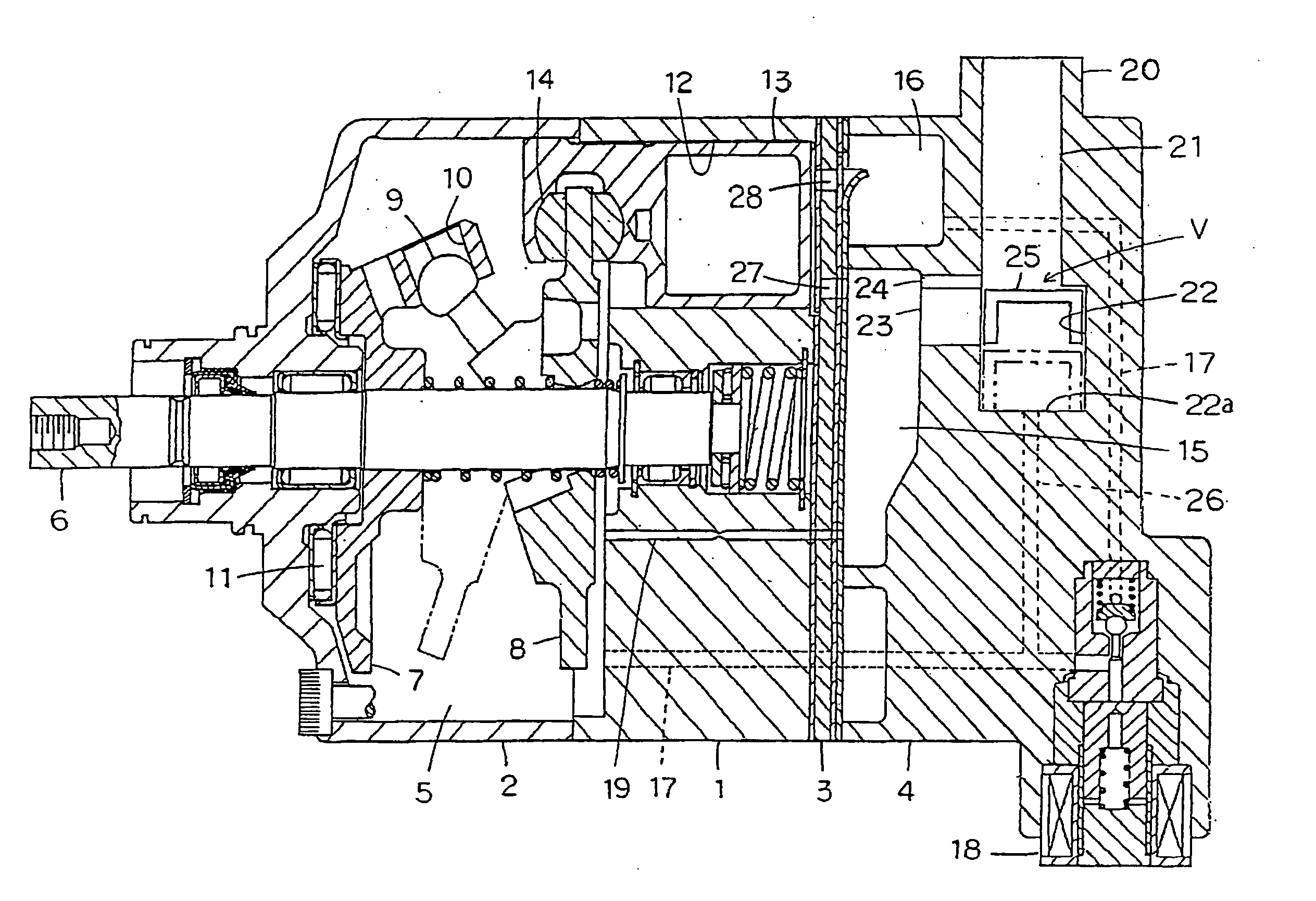
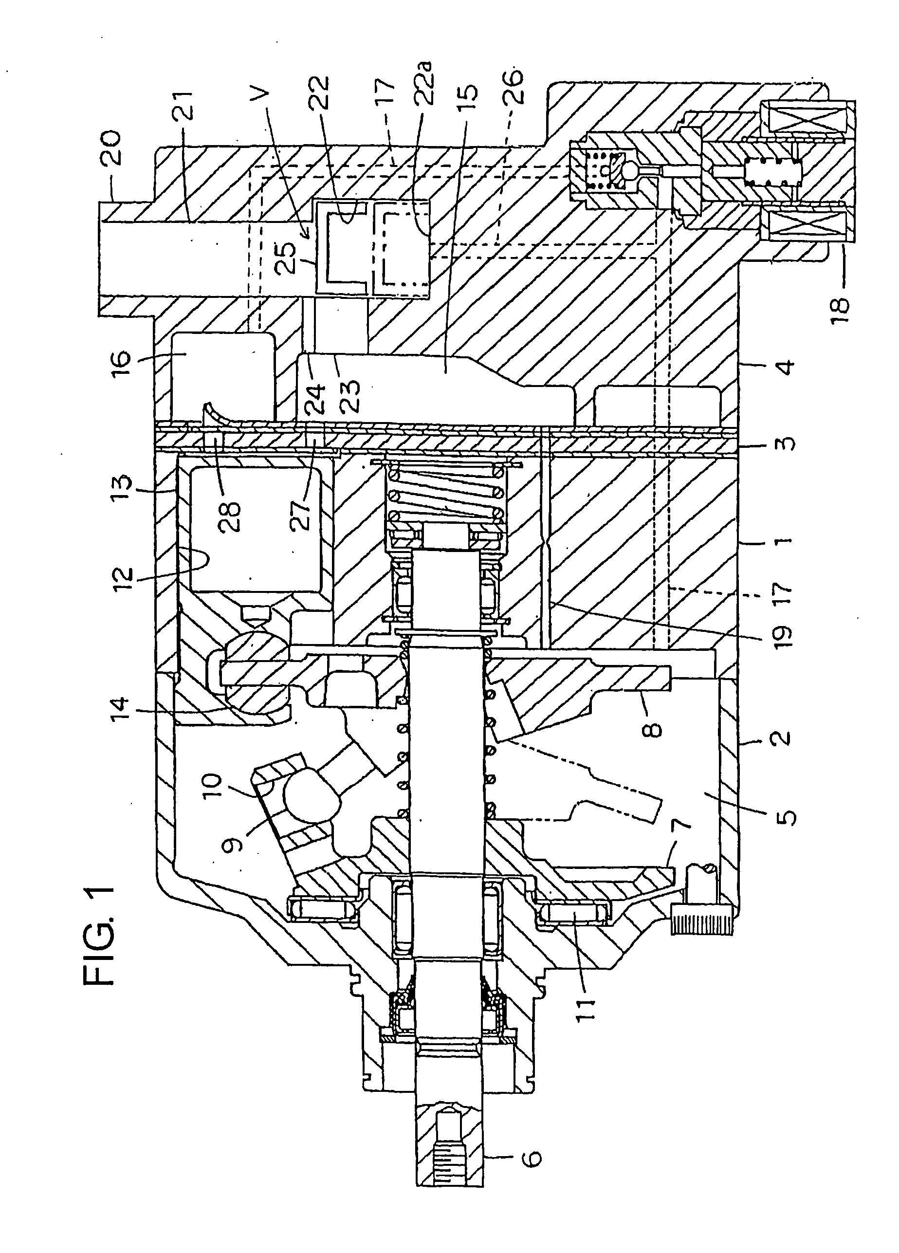
[0022]FIG. 1 shows a construction of a variable displacement compressor according to Embodiment 1. A front housing 2 is connected to the front end portion of a cylinder block 1, and a rear housing 4 is connected to the rear end portion of the cylinder block 1 through the intermediation of a valve forming member 3. A crank chamber 5 is defined by the cylinder block 1 and the front housing 2, and a drive shaft 6 is rotatably supported by the cylinder block 1 and the front housing 2 so as to extend through the crank chamber 5. The forward end portion of the drive shaft 6 protrudes outwardly from the front housing 2 and is connected to a rotary drive source (not shown), such as a vehicle engine or a motor. Inside the front housing 2, a rotary support member 7 is fixed to the drive shaft 6, and a swash plate 8 is mounted so as to be engaged with the rotary support member 7. The swash plate 8 has at its center a through-hole, through which the drive shaft 6 extends, and, in this state, a ...

embodiment 2

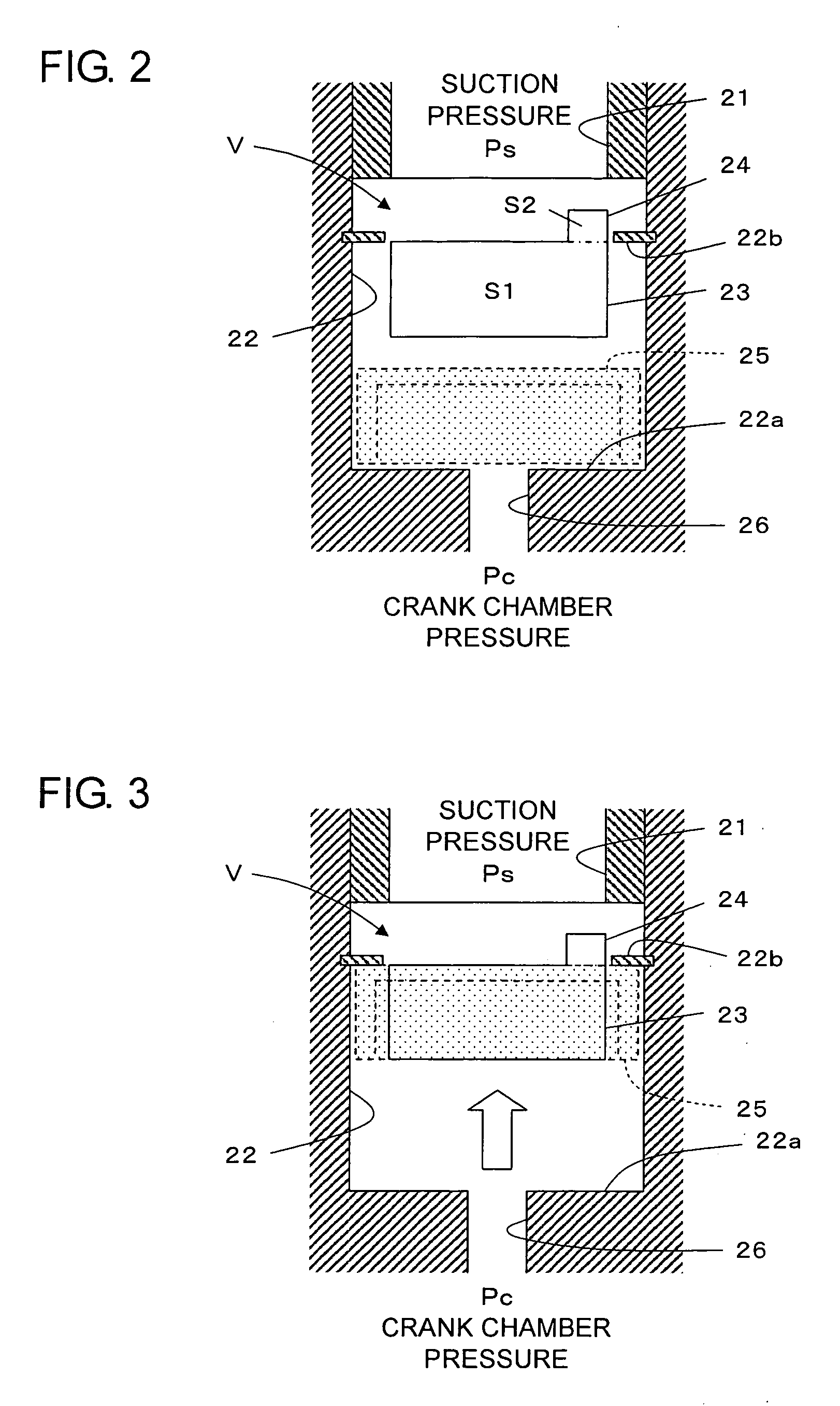
[0036]FIG. 4 shows the construction of the opening control valve of a variable displacement compressor according to Embodiment 2. In the valve chamber 22 of the opening control valve V, a cylindrical valve body 29 is movably accommodated, and, on the rear side of the valve body 29, a cylindrical movable member 30 is movably accommodated. Between the valve body 29 and the movable member 30, there is arranged a spring 31 serving as an urging member urging these two members so as to move them away from each other. Further, in the portion of the inner wall portion of the valve chamber 22 between the valve body 29 and the movable member 30, there is arranged a stopper 32 for regulating the movement of the movable member 30. The suction pressure Ps acts on the front surface of the valve body 29 through the suction passage 21 so as to open the suction ports 23 and 24, and the pressure Pc of the crank chamber 5 acts on the rear surface of the movable member 30 through the communication pass...

embodiment 3

[0043]FIG. 8 shows the construction of a variable displacement compressor according to Embodiment 3 of the present invention. A valve body 42 in the form of a bottomed cylinder is movably accommodated in a valve chamber 41 of the opening control valve V, and on the rear side of the valve body 42, a cylindrical movable member 43 is movably arranged inside a guide portion 44. Between the valve body 42 and the movable member 43, there is arranged a spring 45 serving as an urging member urging them away from each other. A suction port 46 is formed in the side surface of the valve body 42, and the suction port 46 is exposed partially or entirely inside a suction chamber 47 according to the position of the valve body 42 in the valve chamber 41, whereby communication is established between a suction port 48 and the suction chamber 47. That is, based on the position of the valve body 42 inside the valve chamber 41, the effective area of the suction port 46 is adjusted, and the opening of th...


PUM


Abstract

A variable displacement compressor in which variable control of displacement is effected through adjustment of a crank chamber pressure, includes: a suction port; a suction chamber; a suction passage establishing communication between the suction port and the suction chamber; and an opening control valve arranged in the suction passage and adapted to adjust the opening of the suction passage based on a pressure difference between a suction pressure in the suction port and the crank chamber pressure.

Description

BACKGROUND OF THE INVENTION [0001] 1. Field of the Invention [0002] The present invention relates to a variable displacement compressor, and more particularly to a reduction in vibration and noise due to suction pulsation during variable displacement operation. [0003] 2. Description of the Related Art [0004] Conventionally, a piston type compressor is equipped with a stopper so that the suction reed valve may not undergo self-excited vibration at the time of suction. However, in a piston type variable displacement compressor, the suction gas amount differs between the maximum displacement state and the variable displacement state. Thus, when the stopper provided is adjusted to the maximum displacement state, the suction reed valve does not open to a sufficient degree and does not abut the stopper when, in particular, the displacement is small, or when the compressor is started in the OFF state, in which the displacement is minimum. As a result, the suction reed valve generates self-...

Claims


Application Information

Patent Timeline
Patent Type & Authority Applications(United States)
IPC IPC(8): F04B27/10F04B49/22F04B27/08
CPCF04B27/1036F04C28/24F04B49/225H02K7/116H02K7/1823H02K13/00
Inventor MURAKAMI, TOMOHIROHIBINO, SOKICHIHAYASHI, SHIROKIMOTO, YOSHIOKITA, YUSUKEKAYUKAWA, HIROAKI
Owner TOYOTA IND CORP
Why Eureka
Try Eureka