

Piezoelectric fluid pump
- Summary
- Abstract
- Description
- Claims
- Application Information
AI Technical Summary
Benefits of technology
Problems solved by technology
Method used
Image

Examples
second preferred embodiment
[0023] A second preferred embodiment is disclosed by reference to FIGS. 4A-4E. In the second preferred embodiment, 1-way active disc valves 15 and 16 have replaced 1-way passive disc valves 10 and 11 of the first preferred embodiment. 1-way active disc valves 15 and 16 are electrically connected to AC power sources 12 and 13 as to open and close based on electrical signals.
Preferred Active Disc Valves
[0024]FIG. 4F shows a top view of active disc valve 15 and FIG. 4G shows a perspective ¼ cutout section of active disc valve 15. Piezoelectric actuator 15a is bonded to the top of metal disc valve 15b. Piezoelecrtric actuator 15a utilizes the d31 piezoelectric mode of operation (d31 describes the strain perpendicular to the polarization vector of the ceramics).
Operation of Active Disc Valves
[0025]FIGS. 4H and 4I illustrate the operation of the preferred active disc valve. In FIG. 4H no electricity has been applied to the piezoelectric actuator 15a and metal disc valve 15b is sealing...
third preferred embodiment
MEMS Valves
[0032] A third preferred embodiment is disclosed by reference to FIGS. 5A-5F. The third preferred embodiment utilizes two passive MEMS valve arrays.
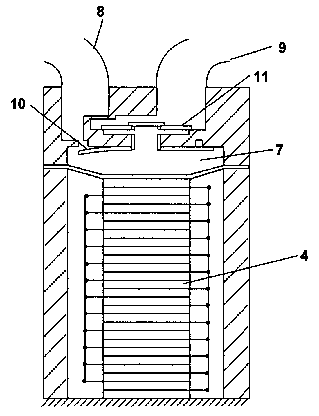
[0033] In the third preferred embodiment, pump 30 is similar to pump 5 shown in FIG. 1, with an exception being that disc valves 10 and 11 of pump 5 have been replaced with I-way passive microvalve arrays 31 and 32, as shown in FIG. 5A. Preferably, microvalve arrays 31 and 32 are two micromachined MEMS valves.
[0034]FIG. 5B shows an enlarged side view of microvalve array 31. Microvalve array 31 is fabricated from silicon, silicone nitride or nickel and includes an array of fluid flow ports 31a approximately 200 microns in diameter. The array of fluid flow ports 31a is covered by diaphragm layer 31b. FIG. 5C shows an enlarged top view of a cutout portion of microvalve array 31. Microvalve array 31 has a plurality of diaphragms 31c covering each fluid flow port 31a.
Operation of a Microvalve Array
[0035] Microvalve arrays 31 a...
fourth preferred embodiment
Active MEMS Valve Operation
[0039] A fourth preferred embodiment is similar to the second preferred embodiment described above in reference to FIGS. 4A-4E, with the exception that active disc valves 15 and 16 (FIG. 4A) are replaced with active microvalve arrays 41 and 42 (FIG. 6A).
[0040]FIG. 6B shows an enlarged side view of microvalve array 41. Microvalve array 41 is fabricated from silicon and includes an array of “Y” shaped fluid flow ports 41a approximately 200 microns in diameter. Preferably, microvalve array 42 is identical to microvalve array 41. Below the junction of each “Y” are heaters 41b. Heaters 41b for microvalve array 41 are electrically connected to power source 51 and heaters 41b for microvalve array 42 are electrically connected to power source 52. Pressure sensor 19 senses the pressure inside fluid chamber 7 and sends a corresponding signal to microprocessor 18. Microprocessor 18 is configured to send control signals to power sources 51 and 52.
Operation of an Ac...
PUM
 Abstract
Description
Claims
Application Information