In-situ blade sharpener

a blade and in-situ technology, applied in grinding machines, other manufacturing equipment/tools, manufacturing tools, etc., can solve the problems of inconvenient removal of blades from driving parts, limited devices, and more difficult use and accurately positioning, so as to achieve maximum sharpening capability, safe in use, and easy, stably and accurately aligned and positioned.

Inactive Publication Date: 2005-11-03
COMBS DAVID
View PDF10 Cites 4 Cited by
  • Summary
  • Abstract
  • Description
  • Claims
  • Application Information

AI Technical Summary

Benefits of technology

[0021] In use, the operator inserts the edge of the blade that needs to be sharpened through a receiving means in the housing and secures the clamp onto the blade which causes the whole sharpening device to be affixed securely to the lawn mower blade still attached to the body of the mower. The operator can adjust the angle of the grinding surface with the pitch adjuster. The operator then uses the drill to rotate the drum to which the drill is attached which causes the grinding surface to rotate freely within the housing of the sharpening device. The operator can re-position the pitch and the blade that is clamped within the housing to maximize the sharpening capability. The use can also manual slide the grinding member along the shaft and across the blade, or a threaded screw-shank mechanism can mechanically cause this action to occur.
[0022] The present invention thus provides an on-site, in-place, portable blade sharpening device for lawn mower blades and the lik

Problems solved by technology

One problem with maintaining a sharp edge on such a blade is the inconvenience involved in removing the blade from its driving member in order to sharpen the blade on a blade sharpening device, such as, for example, a bench mounted grinding wheel.
However there remains problems with such devices due to, inter alia, problems of safety, the ability to monitor the edge sharpening while it is in progress, and accuracy in controlling the angle of the edge being ground since the operator is required to manually hold the device against the blade.
Such a device is very limited in its application being confined to use basically only with the lawn mower design illustrated and can be relatively dangerous to use, with the rotating grinder being exposed to the operator during use.
The device includes no guard for the rotating sharpening members, making it relatively dangerous, and no means are provided to allow the operator to grasp the device at both ends, making it more difficult to use and accurately position.
As above, this approach of direct bracing on the lawn mower structure greatly limits the applicability and use of the device.
Also, as above, the substantial exposure of the rotating sharpening device to the operator makes the device relatively dangerous to use.
Like Holland et al, the Kolling device includes no guard for the rot

Method used


Image

  • In-situ blade sharpener
  • In-situ blade sharpener
  • In-situ blade sharpener

Examples


Embodiment Construction

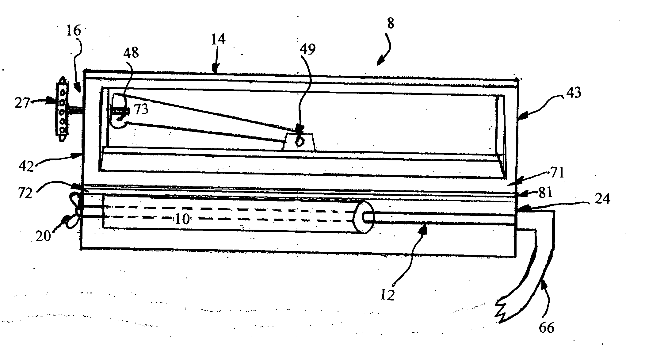
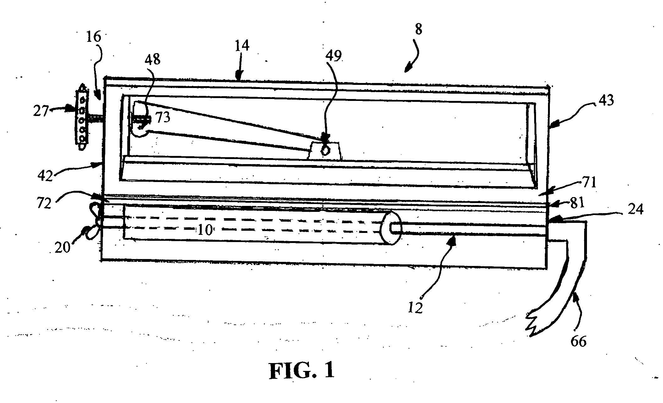
[0028]FIG. 1 shows the preferred, exemplary embodiment of the blade sharpening device 8 of the invention with the main elements of the device including a grinding member 10; a shaft member 12; a housing member 14, which can be transparent if so desired, having an upper plate 71 and a lower plate 72; and a clamping mechanism 16 having a clamping end 27 mounted to an upper plate 71 which is movable in a vertical direction by the clamping mechanism 16. The entire invention can be constructed of any suitable material that has the strength and durability. The preferred material is a composite of man-made organic para-aramid fibers.

[0029] The shaft 12 may be constructed of any material which has sufficient torsional strength to rotate and carry the grinding member 10. Suitable shaft constructing materials include metals, such as steel, fiberglass, and plastics having the required torsional strength. In the preferred embodiment shaft member 12 is constructed of a man-made organic para-ara...


PUM

PropertyMeasurementUnit
Forceaaaaaaaaaa
Angleaaaaaaaaaa
Widthaaaaaaaaaa

Abstract

A blade sharpening device easily connectable to a source of rotating power, such as a battery powered hand drill, and having a housing, a selectably locatable pitch adjuster and a clamping mechanism means for maintaining the housing and grinding surfaces of the sharpening device at a desired grinding angle. The housing extends completely over the width of the rotatable drums wrapped with grinding surface. By clamping the device directly to the blade and stabilizing the device in this position, the operator has greater control and stability of the sharpener when in use on, for example, a lawn mower blade which is still attached to the lawn mower drive shaft at the underside of the lawn mower housing. This on-site, in-place blade sharpening capability eliminates the necessity of removing the blade for its sharpening, while still allowing easy and safe sharpening of the blade.

Description

CROSS REFERNCE TO RELATED APPLICATION [0001] Not Applicable STATEMENT REGARDING FEDERALLY SPONSORED RESEARCH OR DEVELOPMENT [0002] Not Applicable BACKGROUND OF THE INVENTION [0003] The present invention is directed to blade sharpening devices in general and more particularly to blade sharpening devices suitable for on-site, in-place use on blades which are, for example, attached to a driving member, such as, for example, a lawn mower blade, and even more particularly to such a device which has a safety guard and associated means for allowing the operator to manually control the positioning and movement of the sharpening device. In additional to the preferred, exemplary application of lawn mower blades, the device can be used to sharpen other devices, such as, for further example, garden tillers, shovels, hoes, as well as scythes, cane knives, sweepers, bladed “weed eaters”, bush hogs, etc. [0004] It is often the case with a mechanically powered blade, such as the blade of a conventi...

Claims


Application Information

Patent Timeline
IPC IPC(8): B24B1/00B24B3/36B24B21/00
CPCB24B21/002B24B3/36
Inventor COMBS, DAVID
Owner COMBS DAVID
Why Eureka
Try Eureka