Analyte test device

an analytical device and integrated technology, applied in the field of integrated lancing and analytical devices, can solve the problems of piercing the skin of the patient, the process of performing an assay is relatively complicated, and the lancing and glucose measurement operations are performed independently of each other, and achieve the effect of convenient us

Active Publication Date: 2005-11-03
ABBOTT DIABETES CARE INC
View PDF57 Cites 338 Cited by
  • Summary
  • Abstract
  • Description
  • Claims
  • Application Information

AI Technical Summary

Benefits of technology

[0025] It is still another object of the present invention to provide an analyte test device of the type described above which, in conjunction with said compatible analyte test monitor, draws an adequate blood sample with minimal

Problems solved by technology

Typically, the movement of the lancet from its retracted position to its extended position is effected with such force that contact of the moving lancet tip with the skin of a patient results in the piercing of the skin of the patient.
A principal drawback associated with diabetes management systems of the type described above is that the lancing and glucose measurement operations are performed independently of one another.
Furthermore, because the lancing and glucose measurement operations are performed independently of one another, the aforementioned process for performing an assay is relatively complicated and requires a considerably high level of manual dexterity, which is highly undesirable.
As can be appreciated, the requirement that the user store, unwrap, load and discard two separate d

Method used


Image

  • Analyte test device
  • Analyte test device
  • Analyte test device

Examples


first embodiment

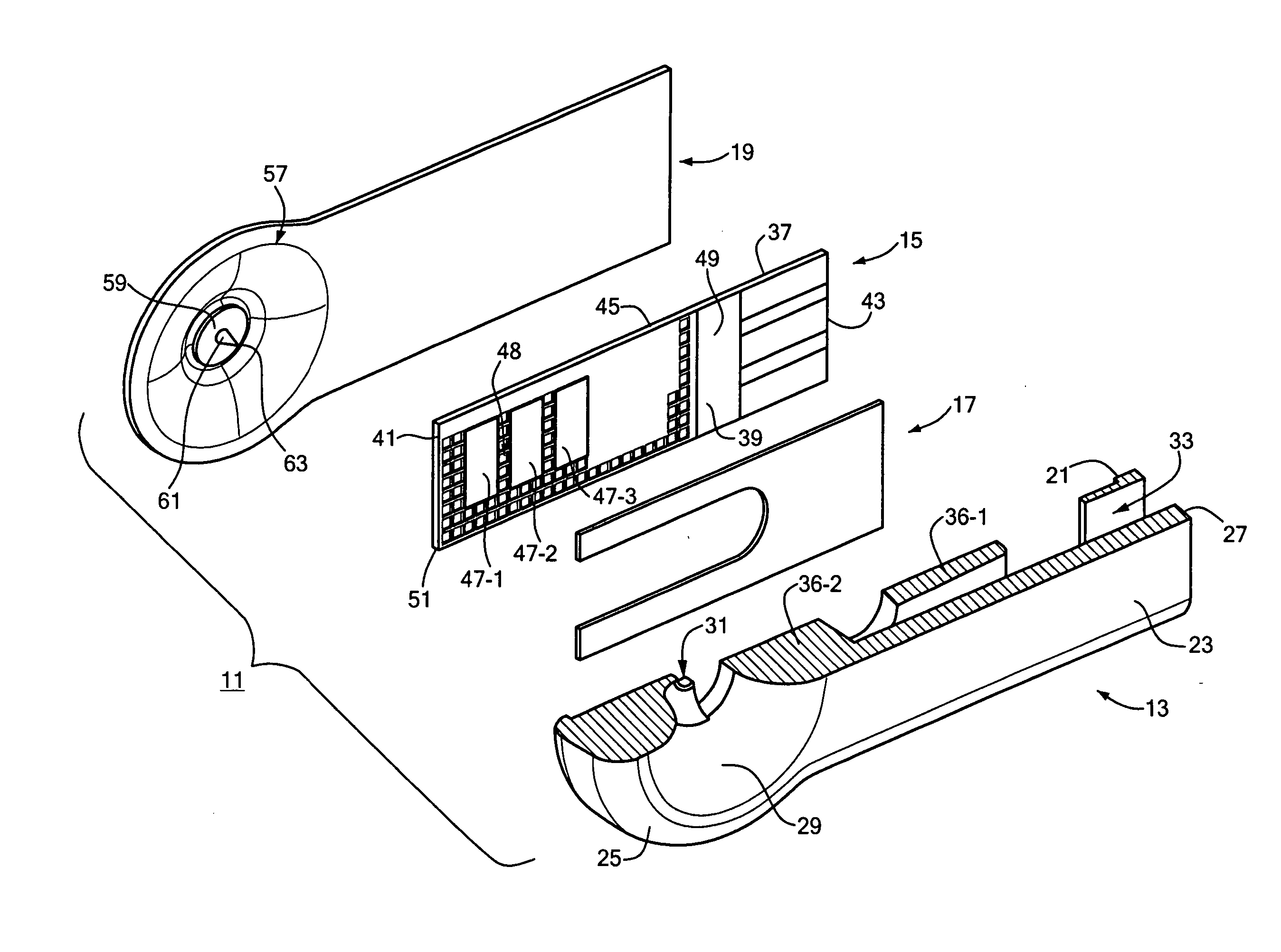
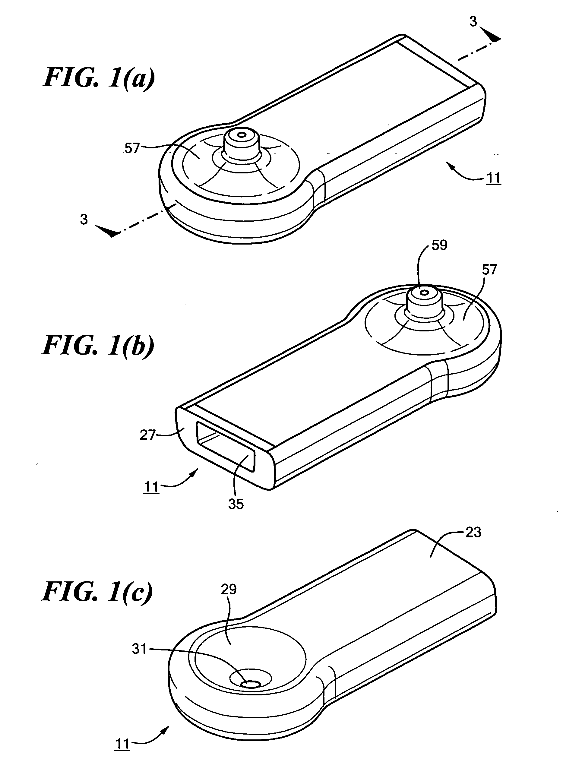
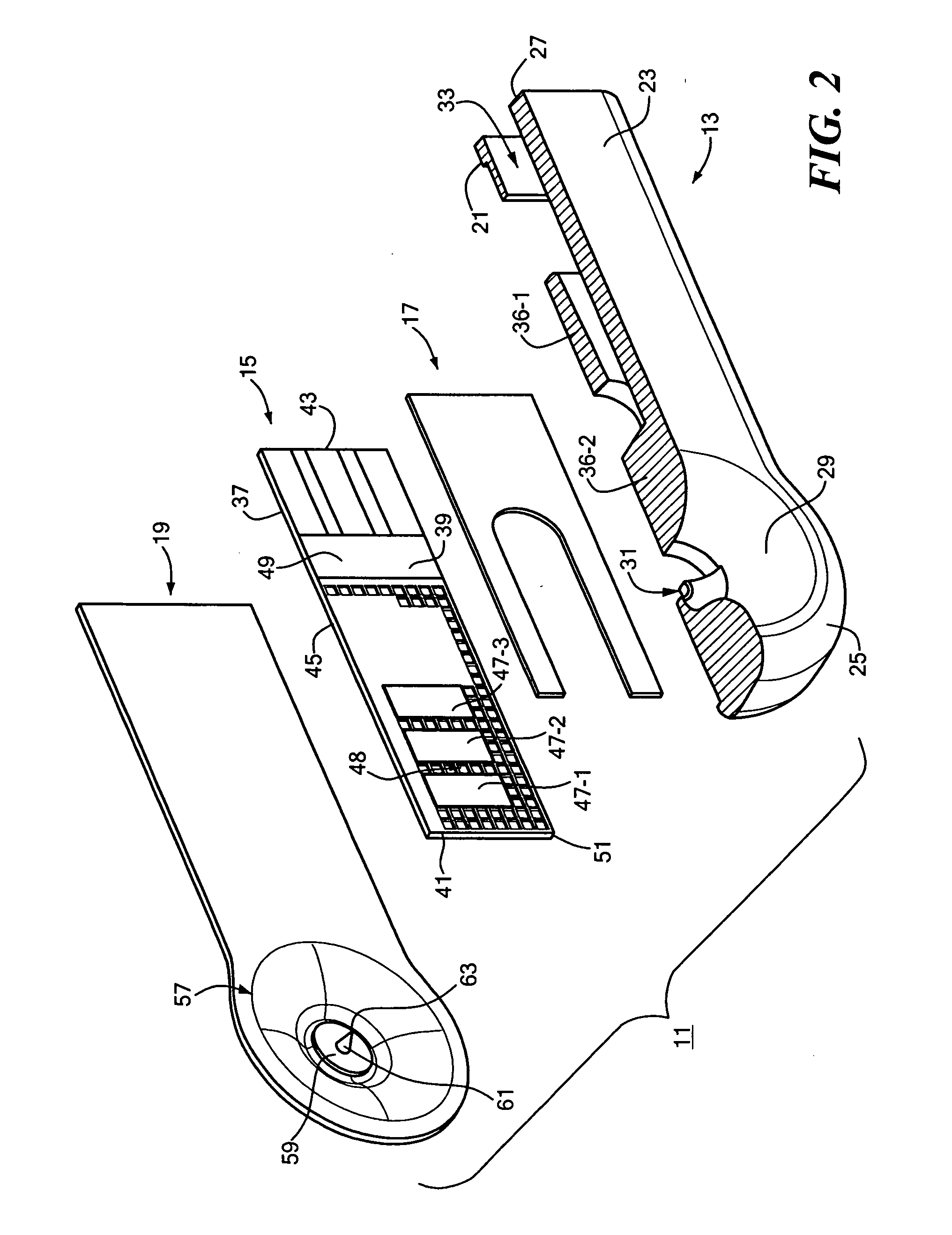
[0050] Referring now to the drawings, there is shown in FIGS. 1(a)-(c) an analyte test device which is constructed according to the teachings of the present invention, the device being identified generally by reference numeral 11. As will be described further in detail below, device 11 is constructed as a unitary, single-use, disposable cartridge which is adapted to be releasably installed into a compatible analyte test monitor (also referred to herein as an analyte test meter). In conjunction with said analyte test monitor, device 11 is capable of performing both (1) a lancing operation on the skin of a patient in order to draw a sample of blood and (2) an analysis of the concentration of a particular analyte in said blood sample. Because device 11 can be used in conjunction with an analyte test monitor to perform both lancing and analyte concentration measurements, device 11 is also referred to herein as an integrated lancing and analytical device (or simply as an integrated dispo...

second embodiment

[0080] Specifically, referring now to FIGS. 4(a)-(c), there is shown an analyte test device which is constructed according to the teachings of the present invention, the device being identified generally by reference numeral 111.

[0081] As seen most clearly in FIGS. 5 and 6, device 111 is similar to device 11 in that device 111 is constructed as a unitary, single-use, disposable cartridge which includes a base 13 and an analyte test strip 15 affixed to base 13 by an adhesive 17.

[0082] Device 111 differs from device 11 in that device 111 comprises a cover 119 which differs in construction from cover 19 in device 11. Specifically, cover 119 is constructed as a thin, transparent sheet of plastic material which is secured to base 13 over test strip 15 to create a unitary, single-use, disposable cartridge with lancing and analyte measurement capabilities. Cover 119 is preferably affixed to base 13 using any conventional means of securement (e.g., by means of ultrasonic welding, an adhesi...

third embodiment

[0084] Referring now to FIGS. 7(a)-(d), there is shown an analyte test device which is constructed according to the teachings of the present invention, the device being identified generally by reference numeral 211. Device 211 is similar to device 11 in that device 211 is constructed as a unitary, single-use, disposable cartridge which is adapted to be releasably installed into a compatible analyte test monitor. In conjunction with said analyte test monitor, device 211 is capable of performing both (1) a lancing operation on the skin of a patient in order to draw a sample of blood and (2) an analysis of the concentration of a particular analyte in said blood sample. Because device 211 can be used in conjunction with an analyte test monitor to perform both lancing and analyte concentration measurements, device 211 is also referred to herein as an integrated lancing and analytical device (or simply as an integrated disposable). Preferably, device 211 can be mass produced with each ind...


PUM

PropertyMeasurementUnit
Angleaaaaaaaaaa
Concentrationaaaaaaaaaa
Flexibilityaaaaaaaaaa

Abstract

An analyte test device is constructed as an integrated, single-use, disposable cartridge which can be releasably installed into a compatible analyte test monitor. In use, the device can be used in conjunction with the monitor to lance the skin of a patient to create a blood sample, express the blood sample from the wound site using vacuum forces and calculate the concentration of a particular analyte in the expressed blood sample. In one embodiment, the device includes a base which includes a top surface and a bottom surface. The base is also shaped to define an aperture which extends transversely through its top and bottom surfaces. An electrochemical test sensor is affixed to the base in such a manner so that a vacuum path is at least partially defined between the base and the test sensor, the vacuum path being in fluid communication with the aperture. A cover is affixed to the top surface of the base over the aperture, the cover comprising a flexible dome-shaped member and a lancet coupled to the member, the lancet being orientated such that its longitudinal axis extends at an approximate right angle relative to the longitudinal axis of the test sensor. The bottom surface of the base is shaped to include a skin receiving surface which at least partially defines the aperture in the base, the skin receiving surface having a steep inward contour to distend the skin of the patient when pressed thereagainst.

Description

BACKGROUND OF THE INVENTION [0001] The present invention relates generally to integrated lancing and analytical devices and more particularly to a novel integrated lancing and analytical device. [0002] There are many medical conditions which require frequent measurement of the concentration of a particular analyte in the blood of a patient. For example, diabetes is a disease which typically requires a patient to routinely measure the concentration of glucose in his / her blood. Based upon the results of each blood glucose measurement, the patient may then require a particular drug treatment (e.g., an injection of insulin) in order to regulate that the blood glucose level of the patient remains within a specified range. Exceeding the upper limit of said range (hyperglycemia) or dropping beneath the lower limit of said range (hypoglycemia) should be avoided with as much diligence as possible to prevent the patient from experiencing serious medical complications which include, inter alia...

Claims


Application Information

Patent Timeline
IPC IPC(8): A61B5/00A61B5/15
CPCA61B5/1411A61B2562/0295A61B5/1486A61B5/14532A61B5/150022A61B5/150099A61B5/150229A61B5/150305A61B5/150358A61B5/150435A61B5/150534A61B5/150969A61B5/15144A61B5/157
Inventor MACE, CHAD HAROLDYANG, PAUL SENSHAHROKNI, FARZAD
Owner ABBOTT DIABETES CARE INC
Why Eureka
Try Eureka