[0010] Accordingly, a need has arisen to provide a parallel-flow type heat exchanger, in which a cross-sectional area of at least one header pipe is increased, which may employ an offset disposition of the header pipe in a direction of air flow across the heat exchanger without increasing the tube
insertion length into the header pipe or a reduction of a
diameter of a unit to be contained in the header pipe, or both. It is an
advantage of such heat exchangers that a decrease of a
pressure resistance of the header pipe may be reduced or eliminated. Further, a lighter weight and lower cost heat exchanger may be achieved while increasing the productivity heat exchanger manufacturing methods.
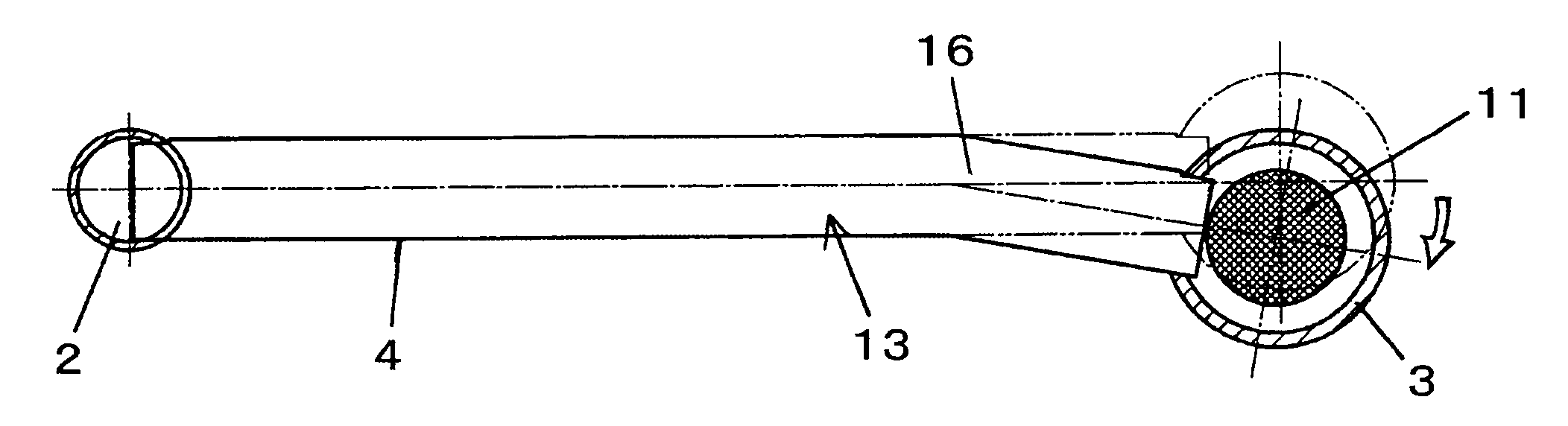
[0012] In such heat exchangers, because the heat exchanger core, e.g., the heat exchanger core through all heat transfer tubes, is bent, so that relative to the center portion of the heat exchanger core, at least one of the pair of header pipes is offset in the direction of air flow across the heat exchanger. For example, when an adjacent component, e.g., a radiator, is present on a downstream side in the air flow direction, and if it is desirable to prevent contact between that component and an enlarged header pipe, the heat exchanger core may be bent toward an upstream side in the air flow direction, i.e. away from the adjacent component. Alternatively, when an adjacent component e.g., a radiator, is present on an upstream side in the air flow direction, the heat exchanger core may be bent toward a downstream side in the air flow direction, i.e., towards the adjacent component. Therefore, in a parallel-flow type heat exchanger for which it is desirable to increase a cross-sectional area of at least one header pipe, a gap between an adjacent component, e.g., a radiator, and the heat transfer tubes of the heat exchanger core may be reduced. Namely, an offset disposition of the header pipe in the direction of air flow across the heat exchanger may be achieved, without increasing the length of tube
insertion into the header pipe and without decreasing the
diameter of a unit, e.g., a unit comprising a
desiccant, contained in the header pipe.
[0013] Further, in this heat exchanger, the above-described at least one header pipe may be formed from a pipe having a circular cross-section. Thus, the header pipes' inner cross-sectional shape may be circular. Therefore, an
internal pressure is received uniformly by an inner surface of the header pipe, and even if a large
internal pressure is applied, deformation of the header pipe may be reduced or eliminated, and a reduction of the
pressure resistance of the header pipe may be reduced or eliminated. Moreover, because a thickened portion of the head pipe is not necessary, the productivity of methods for manufacturing such heat exchangers may be increased, and a lighter weight and lower cost heat exchanger may be achieved than known heat exchangers.
[0016] Thus, in heat exchangers according to the present invention, a structure may be employed, in which the header pipe is offset to one side of the direction of air flow across the heat exchanger without decreasing the
pressure resistance of the header pipe and without increasing the insertion length of heat transfer tubes or decreasing the
diameter of a unit contained in the header pipe, or both. Such heat exchangers have an outer shape permitting an efficient
layout while achieving a desirable performance. Therefore, even if components, such as a radiator, are disposed adjacent to the heat exchanger, as described above, the heat
radiation portions of the radiator and the heat transfer tubes need not be greatly separated from each other. Thus, the thickness of the heat exchanger, e.g., the condenser, and another component, e.g., the radiator need not increase; and an amount of air passing through the heat exchanger and another adjacent component need not decrease due to air leakage between the heat exchanger and the other component.

