Distributed arc electroerosion

a distribution arc and electroerosion technology, applied in the field of manufacturing processes, can solve the problems of corresponding time and money loss, particularly complex and expensive precision parts are the typical bladed disks, blisks, and blisk materials are typically superalloys with enhanced strength, and achieve even higher machining rates

Inactive Publication Date: 2005-11-10
GENERAL ELECTRIC CO
View PDF23 Cites 60 Cited by
  • Summary
  • Abstract
  • Description
  • Claims
  • Application Information

AI Technical Summary

Benefits of technology

[0023] Accordingly, it is desired to provide an electroerosion machining apparatus and process capa

Problems solved by technology

Damage to the workpiece during machining may require scrapping thereof, with an attendant loss in time and money corresponding therewith.
A particularly complex and expensive precision part is the typical bladed disk, or blisk, found in gas turbine engines.
The blisk material is typically a superalloy having enhanced strength, and is correspondingly expensive.
Since the blisk workpiece requires multiple stages of manufacture and machining immediately prior to the forming of the airfoils therein considerable time and money are invested in the workpiece.
And, as each of the multitude of airfoils around the blisk perimeter is machined, additional time and expense are invested which further increases the cost of the blisk.
Unacceptable damage to any one of the blisk airfoils or the supporting rotor disk itself during the various stages of

Method used


Image

  • Distributed arc electroerosion
  • Distributed arc electroerosion
  • Distributed arc electroerosion

Examples


Embodiment Construction

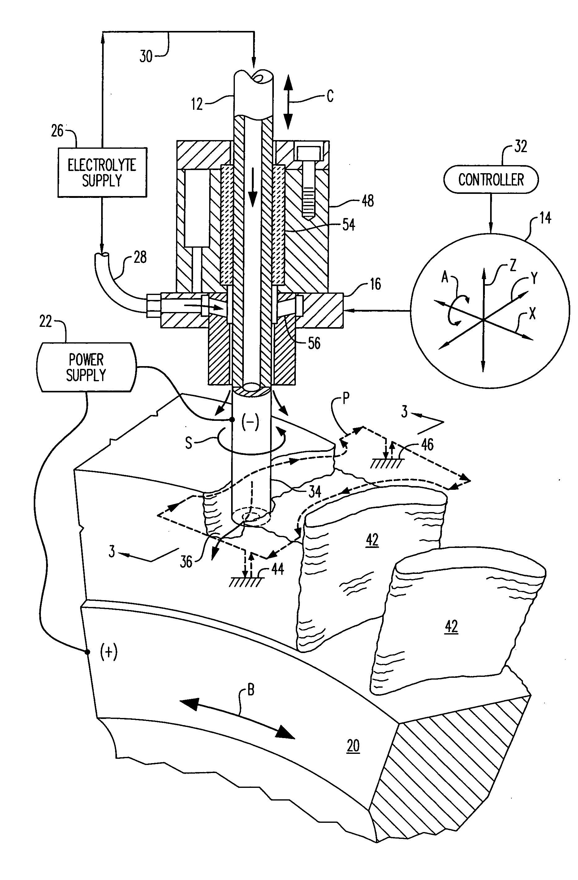
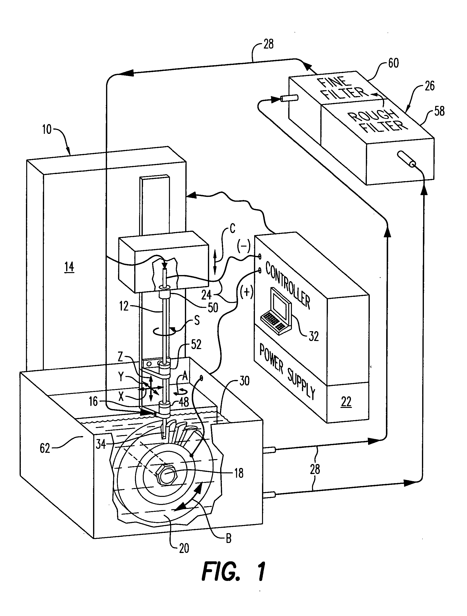
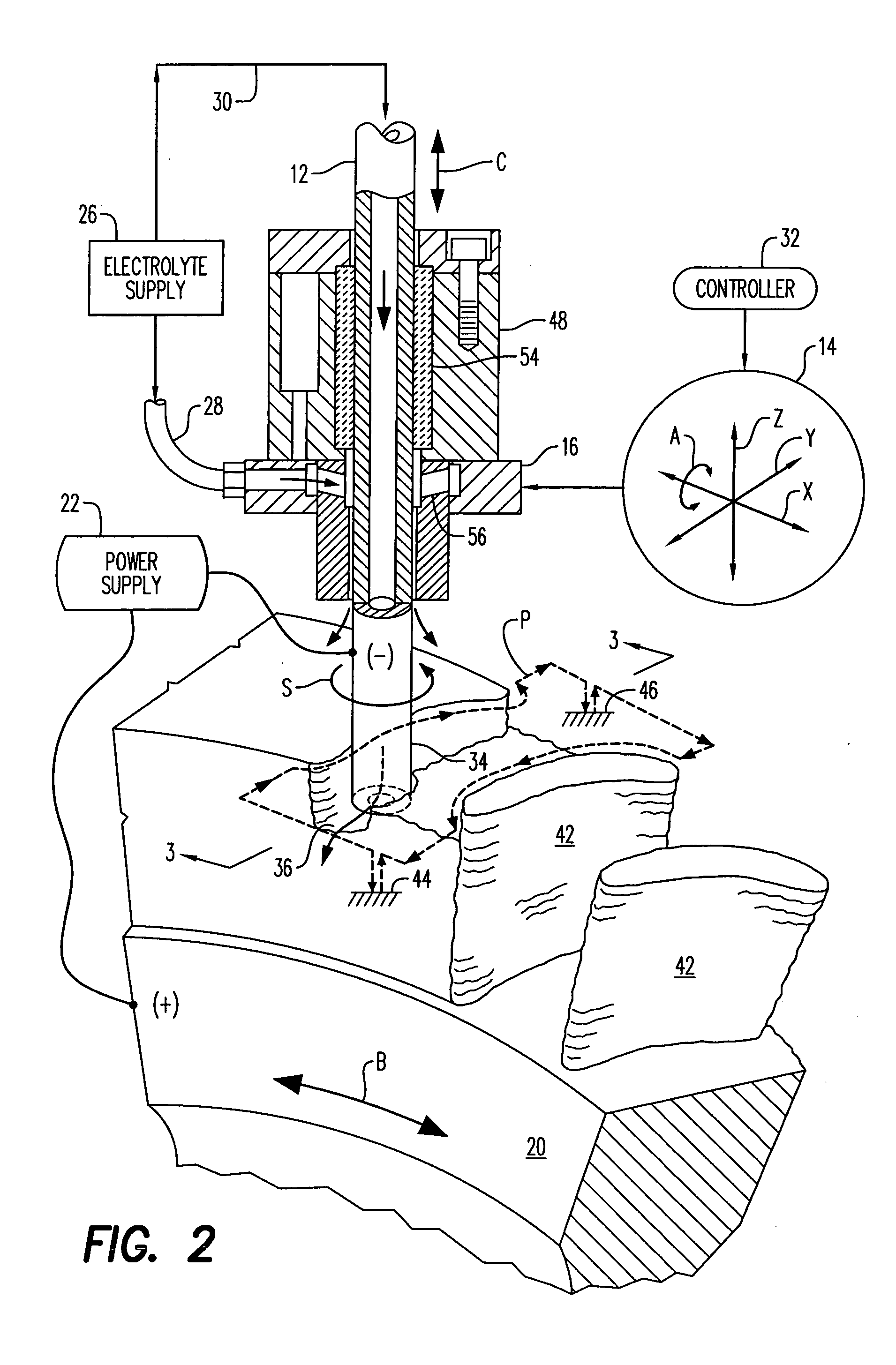
[0029] Illustrated schematically in FIG. 1 is an electroerosion machine or apparatus 10 including a tubular cutting tool or electrode 12. The apparatus includes a multiaxis, numerically controlled (NC) machine 14 which includes a tool head 16 that supports the electrode for rotation or spinning S thereof, and multiple axes of movement during operation. The machine also includes a suitable support table in the exemplary form of a rotary spindle 18 which supports a workpiece 20, preferably with an additional axis of movement.

[0030] Means in the form of a conventional direct current (DC) power supply 22 are provided for carrying electrical power through the electrode 12 and workpiece 20 during operation. The power supply includes suitable electrical leads 24 correspondingly joined to the electrode 12 as a cathode (−) and the workpiece as an anode (+) in one embodiment. In alternate embodiments, the polarity may be reversed with an anode electrode and a cathode workpiece.

[0031] Since ...


PUM

PropertyMeasurementUnit
Timeaaaaaaaaaa
Volumeaaaaaaaaaa
Electric potential / voltageaaaaaaaaaa

Abstract

An electroerosion apparatus includes a tubular electrode supported in a tool head in a multiaxis machine. The machine is configured for spinning the electrode along multiple axes of movement relative to a workpiece supported on a spindle having an additional axis of movement. A power supply powers the electrode as a cathode and the workpiece as an anode. Electrolyte is circulated through the tubular electrode during operation. And, a controller is configured to operate the machine and power supply for distributing multiple electrical arcs between the electrode and workpiece for electroerosion thereof as the spinning electrode travels along its feedpath.

Description

BACKGROUND OF THE INVENTION [0001] The present invention relates generally to manufacturing processes, and, more specifically, to machining. [0002] Precision machining is commonly effected using multiaxis numerically controlled (NC) milling machines. The cutting tool is suspended from a tool head which typically has three orthogonal axes of translation and one or more additional axes of rotation corresponding therewith. The workpiece or part to be machined is fixedly mounted to a bed which may impart additional axes of translation or rotary movement thereto. [0003] During operation, the NC machine is programmed in software for controlling the machining or cutting path of the tool for precisely removing material from the workpiece to achieve the desired final dimensions thereof. The typical milling machine includes a rotary cutting tool having a controlled feedpath for removing material from the workpiece in successive passes finally approaching the desired machined configuration. [0...

Claims


Application Information

Patent Timeline
IPC IPC(8): B23H1/02B23H7/26B23H1/00B23H7/32B23H9/10B23K9/013
CPCB23H1/022B23H7/32B23K9/013B23H2400/10B23H9/10B23H5/02
Inventor LAMPHERE, MICHAEL SCOTTWEI, BINYUAN, RENWEIWESSELS, JEFFREY FRANCIS
Owner GENERAL ELECTRIC CO
Why Eureka
Try Eureka