Method of manufacturing substrate for ink jet recording head and method of manufacturing recording head using substrate manufactured by this method

a technology of ink jet recording head and manufacturing method, which is applied in the direction of recording apparatus, photomechanical apparatus, instruments, etc., can solve the problems of heat generating resistive layer broken wires, etc., and achieve the effect of reducing the occurrence of broken wires and improving the durability of the heat generating resistive body

Active Publication Date: 2005-11-10
CANON KK
View PDF19 Cites 30 Cited by
  • Summary
  • Abstract
  • Description
  • Claims
  • Application Information

AI Technical Summary

Benefits of technology

[0008] An object of the present invention is to provide a method of manufacturing a substrate for an ink jet recording head which suppresses the occurrence of broken wires due to thermal stresses in a substrate for an ink jet recording head having a heat generating resistive layer covering electrode layers and in which the durability of a heat generating resistive body is improved, and a method of manufacturing an ink jet recording head.
[0009] Another object of the present invention is to provide a method of manufacturing a substrate for an ink jet recording head which improves the step coverage of a protective film covering a heat generating resistive layer so that sufficient durability of a heat generating resistive body can be ensured even when the protective film is made thin, whereby the heat generated in the heat generating resistive body is efficiently used in the discharge of ink to save power, and a method of manufacturing an ink jet recording head.

Problems solved by technology

This poses a problem to be solved when a record image of higher grade is sought for.
This poses a problem.
In addition to these problems, when a heat generating resistive body is continuously driven at high frequencies in order to adapt to high speed, high definition recording for which requirements are increasing today, there is a strong possibility that stronger thermal stresses may be generated, thereby causing broken wires in the heat generating resistive layer.

Method used


Image

  • Method of manufacturing substrate for ink jet recording head and method of manufacturing recording head using substrate manufactured by this method
  • Method of manufacturing substrate for ink jet recording head and method of manufacturing recording head using substrate manufactured by this method
  • Method of manufacturing substrate for ink jet recording head and method of manufacturing recording head using substrate manufactured by this method

Examples


Embodiment Construction

[0021] The present invention will be concretely described below by using embodiments with reference to the accompanying drawings as required.

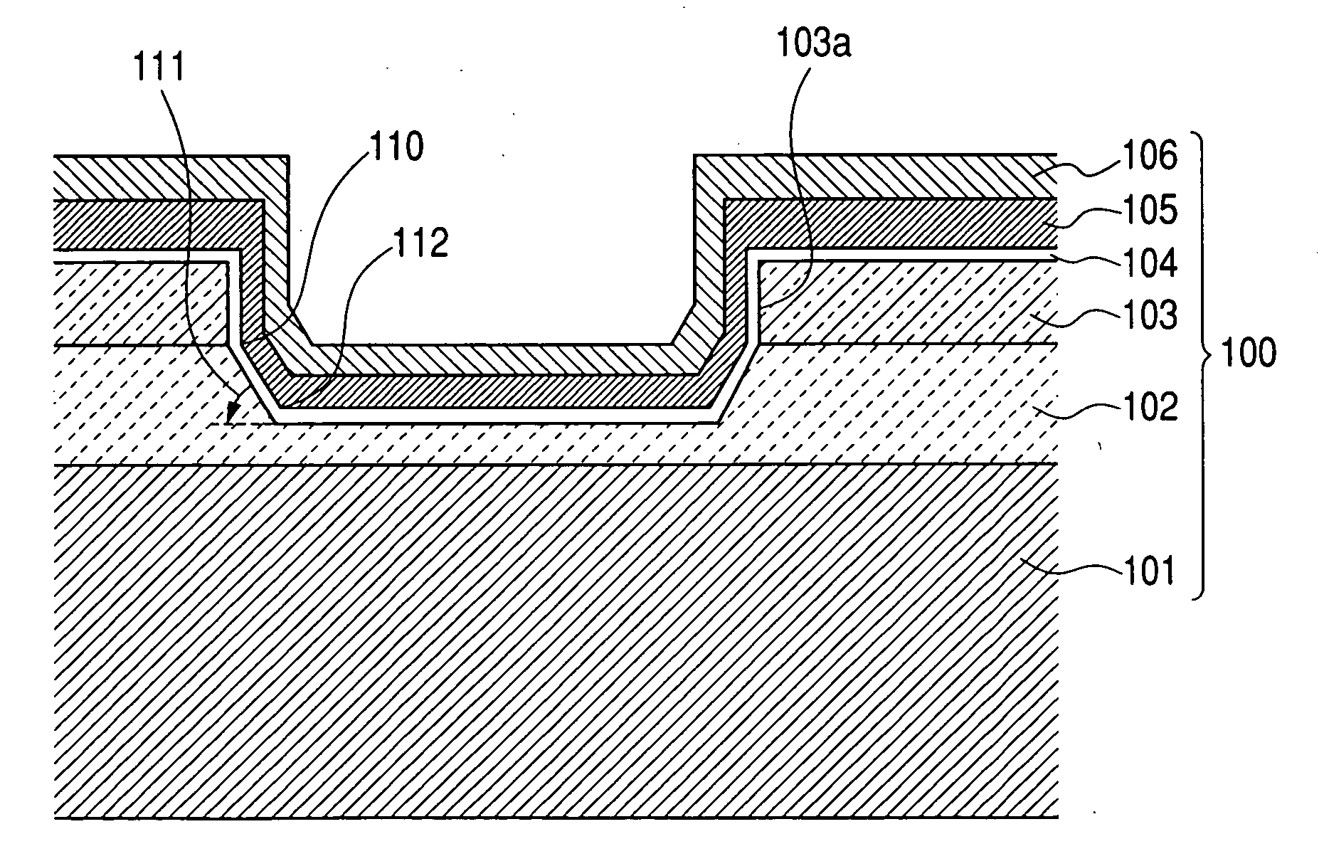
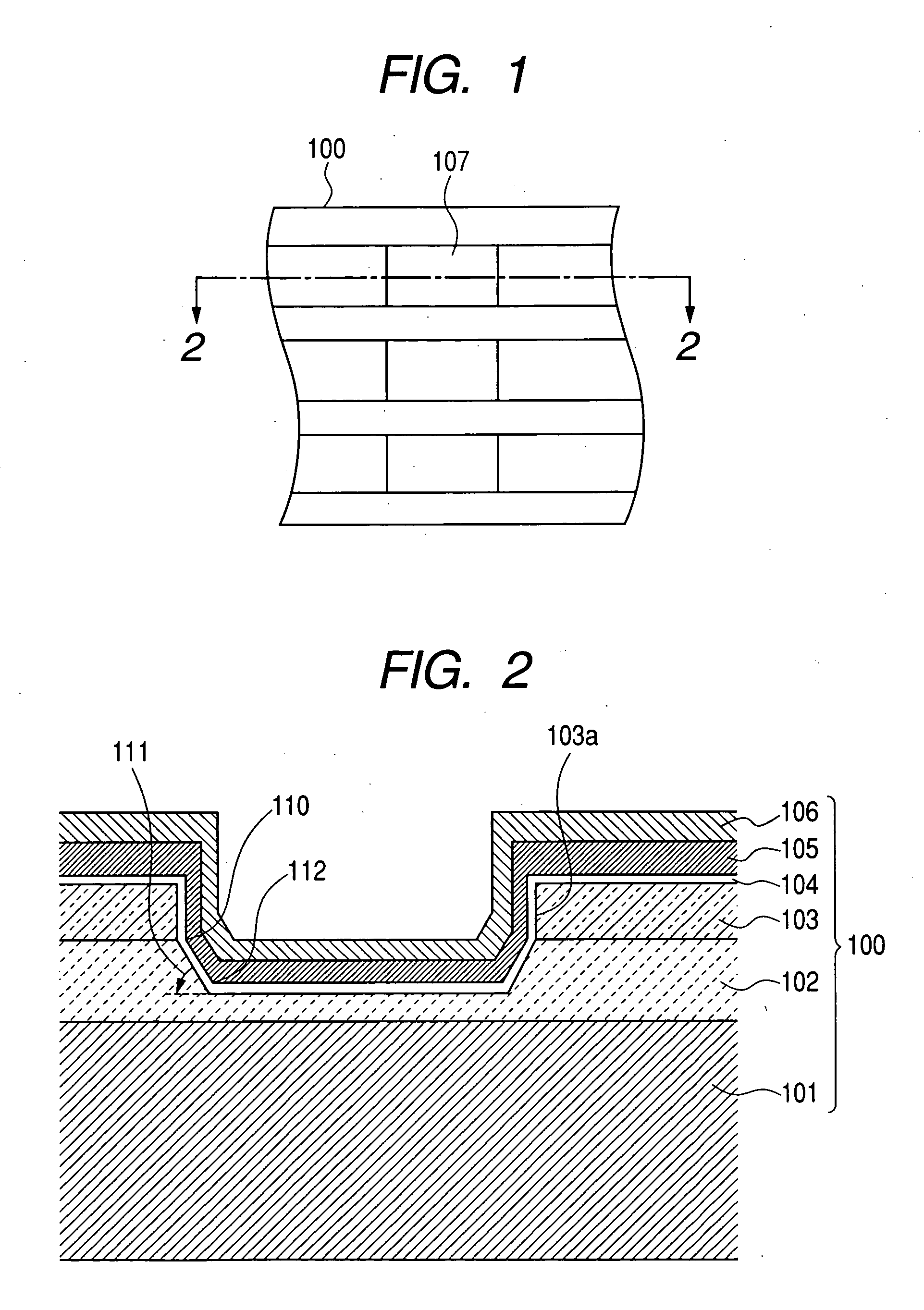
[0022]FIG. 1 is a schematic plan view that shows the construction of a substrate for an ink jet recording head according to the present invention and, particularly, a plan view that shows the area near a heat acting portion 107 of a substrate for a head. FIG. 2 is a schematic sectional view of the section taken along the line 2-2 in FIG. 1.

[0023] In a substrate for an ink jet recording head of the form shown in FIG. 2, a heat generating resistive layer 104 covers a pair of electrode layers 103 formed on a lower layer (a heat accumulation layer) 102, which is formed on a surface of a board 101, and in the lower layer 102 there is formed a recess in a position corresponding to a section between the pair of electrode layers.

[0024] Heat generated in the heat generating resistive layer 104 positioned between the pair of electrode layers 103 by su...


PUM

PropertyMeasurementUnit
taper angleaaaaaaaaaa
thicknessaaaaaaaaaa
thicknessaaaaaaaaaa

Abstract

In order to form a more homogenous heat generating resistive layer, the present invention provides a method of manufacturing a substrate for an ink jet recording head having a support which has an insulative layer on its surface, a pair of electrode layers disposed on the surface of the support, and a heat generating resistive layer which continuously covers the pair of electrode layers and a section between the pair of electrode layers. The method includes the step of forming an electrode layer on the support and the step of forming the pair of electrode layers by etching the electrode layer. In the step of forming the pair of electrode layers by etching the electrode layer, by etching a surface portion of the insulative layer positioned between the pair of insulative layers, a recess is formed in the surface portion of the insulative layer.

Description

BACKGROUND OF THE INVENTION [0001] 1. Field of the Invention [0002] The present invention relates to a method of manufacturing an ink jet recording head and a method of manufacturing a recording head using the substrate manufactured by this method. [0003] 2. Related Background Art [0004] An ink jet recording head that has, as its component parts, an orifice provided to discharge a liquid and a heat acting portion (a heat generating portion), which is a portion in communication with this orifice and in which heat energy to discharge liquid droplets acts on the liquid, is described, for example, in FIGS. 1 and 3 of the Japanese Patent Application Laid-Open No. S60-159062. A structure corresponding to FIG. 1 of this patent publication is shown in FIG. 9. In this structure, a heat generating resistive layer 204, which generates heat when it is energized, is provided on a lower layer 202 of a substrate 200, and a pair of electrodes 203 is provided on the heat generating resistive layer 2...

Claims


Application Information

Patent Timeline
Patent Type & Authority Applications(United States)
IPC IPC(8): B41J2/14B41J2/16
CPCB41J2/14129B41J2/1601B41J2/1628B41J2/1646B41J2/1631B41J2/1642B41J2/1629B41J2/1639B41J11/0095B41J13/103B41J2002/14475
Inventor KOMURO, HIROKAZUOZAKI, TERUOKOYAMA, SHUJIKUBO, KOUSUKETERUI, MAKOTOHAYAKAWA, KAZUHIROKANRI, RYOJIKATO, MASATAKA
Owner CANON KK
Why Eureka
Try Eureka