Memory control device having less power consumption for backup

Inactive Publication Date: 2005-11-10
CANON KK
View PDF8 Cites 81 Cited by
  • Summary
  • Abstract
  • Description
  • Claims
  • Application Information

AI Technical Summary

Benefits of technology

[0008] An object of the present invention is to provide a memory control device in which supplying of power to a memory controller is stopped upon battery back-up of a DRAM to re

Problems solved by technology

However, in the above conventional procedure (1), since the battery power is consumed by the memory controller itself, as well as the SDRAM to be backed up, there was a disadvantage that a back-up sustaining time is short.
On the other hand, in the conventional procedure (2), since the power to the memory controller is stopped, although the disadvantage encounte

Method used


Image

  • Memory control device having less power consumption for backup
  • Memory control device having less power consumption for backup
  • Memory control device having less power consumption for backup

Examples


Example

First Embodiment

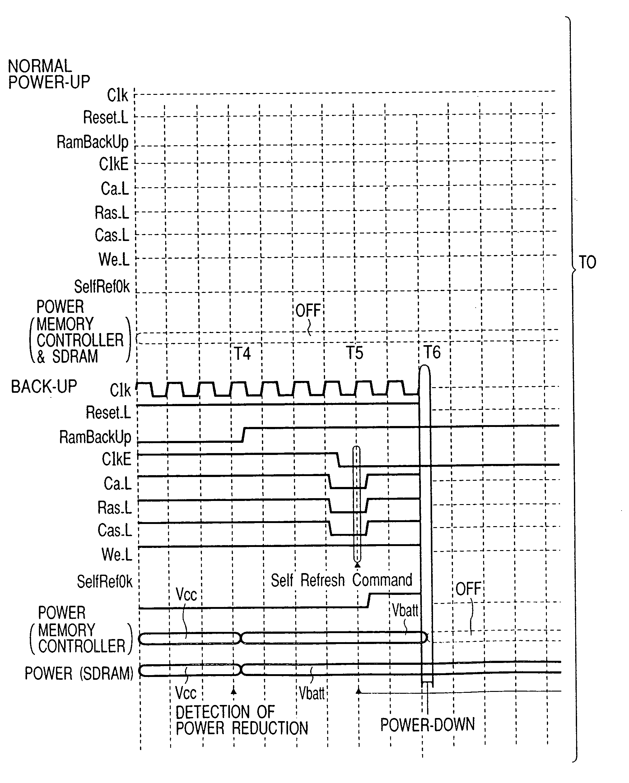
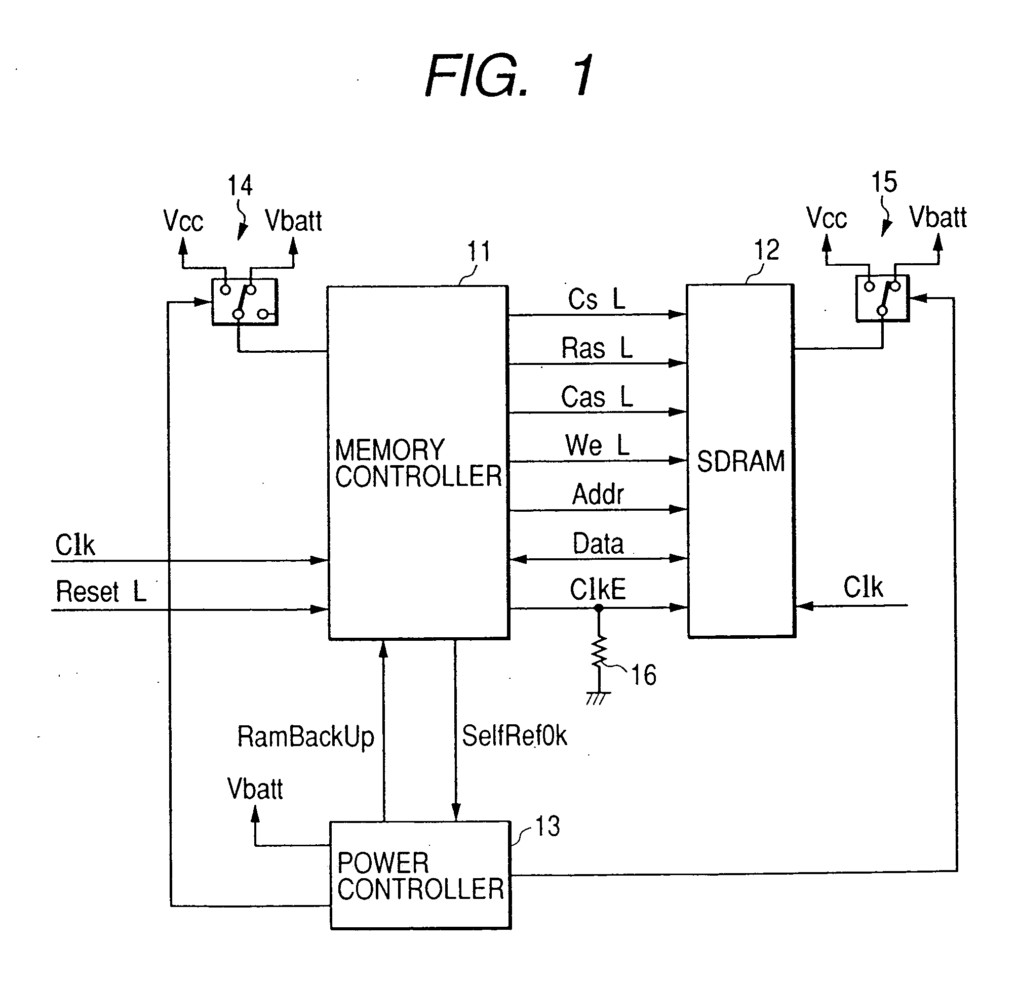
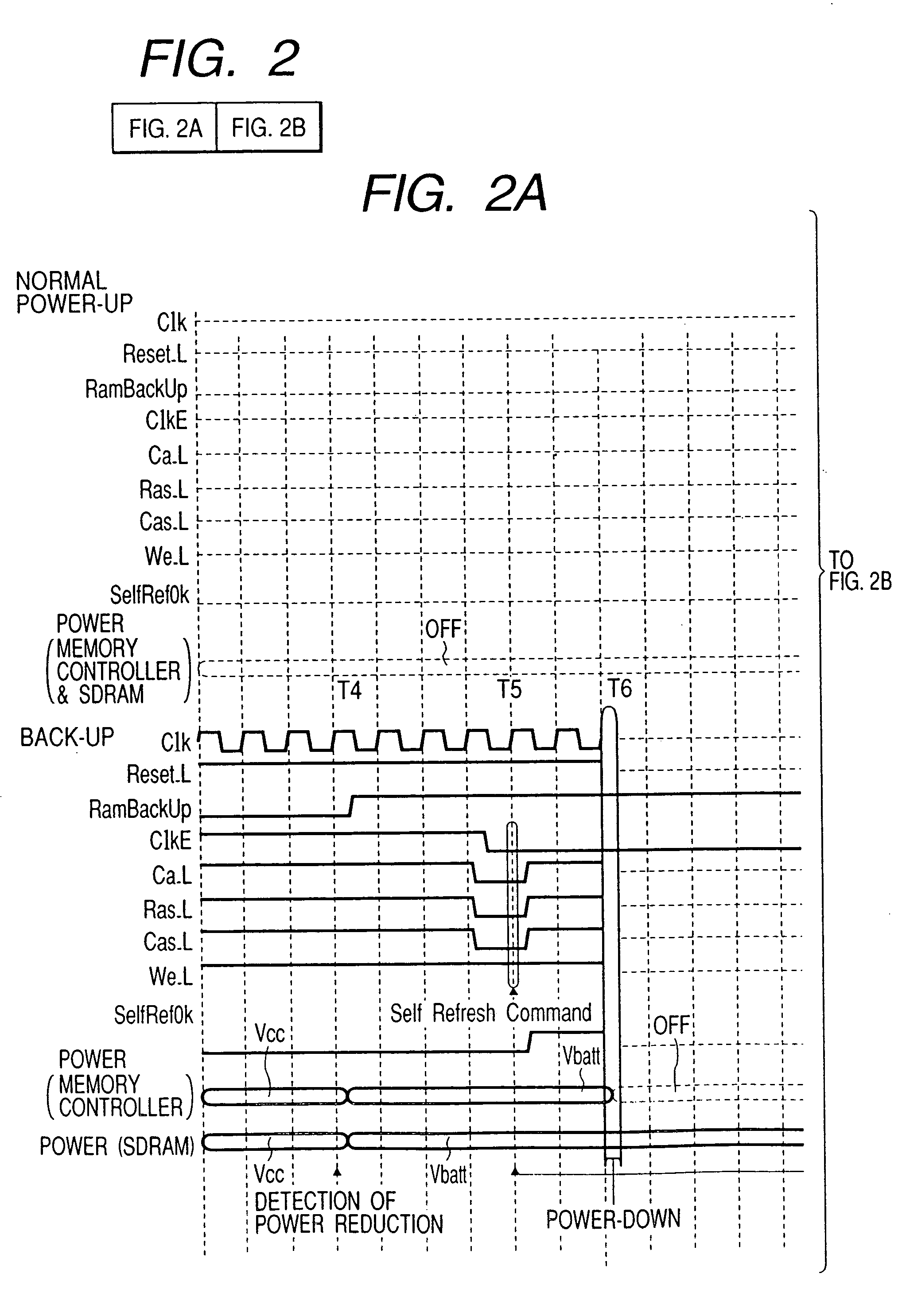
[0016] Now, a first embodiment of the present invention will be explained with reference to FIGS. 1, 2A and 2B. FIG. 1 shows a construction of a memory control device according to the first embodiment. The memory control device includes a memory controller 11 and a power controller 13 for a DRAM 12.

[0017] In FIG. 1, the memory controller 11 serves to control an operation of a memory (SDRAM 12). The SDRAM 12 is a memory to be controlled. The power controller 13 serves to monitor and control a main power supply Vcc for the memory controller 11 and a battery power supply Vbatt for the SDRAM 12. A switch 14 serves to switch a power supply to the memory controller 11 to either the main power supply Vcc or the battery power supply Vbatt under the control of the power controller 13. A switch 15 serves to switch a power supply to the SDRAM 12 to either the main power supply Vcc or the battery power supply Vbatt under the control of the power controller 13. A pull-down resi...

Example

Second Embodiment

[0038] Next, a second embodiment of the present invention will be explained with reference to FIGS. 3, 4A and 4B. FIG. 3 shows a construction of a memory control device according to the second embodiment. In FIG. 3, the same elements as those in the first embodiment (FIG. 1) are designated by the same reference numerals, and explanation thereof will be omitted.

[0039] As shown in FIG. 3, in an arrangement according to the second embodiment, the switch 14 in the first embodiment (FIG. 1) is omitted, and the supplying power to a memory controller 31 is performed by the main power supply Vcc alone, and the power supply of the memory controller 31 is not switched. Further, in the first embodiment, although the signal SelfRefOK was outputted from the memory controller 11 to the power controller 13, in the second embodiment, the signal SelfRefOK is not outputted from the memory controller 31 to a power controller 33. The other arrangements according to the second embodim...


PUM


Abstract

When power stoppage of a main power supply is detected during a normal operation, a power controller switches a power supply for a DRAM from the main power supply to a battery power supply and makes an instruction signal for instruction a self-refresh mode to a memory controller active. In response to this, the memory controller changes a clock enable signal for the DRAM to a low level to establish the self-refresh mode of the DRAM, and, after, the self-refresh mode of the DRAM is established, supplying of power to the memory controller is stopped. The clock enable signal for the DRAM is maintained to the low level by pull-down resistance even when the supplying of power to the memory controller is stopped from a condition that the signal is changed to the low level in the self-refresh mode, thereby maintaining the self-refresh mode of the DRAM.

Description

BACKGROUND OF THE INVENTION [0001] 1. Field of the Invention [0002] The present invention relates to a memory control device having a memory controller for controlling an operation of DRAM such as a synchronous dynamic random access memory (SDRAM) and a power controller for controlling a power supply for the memory. [0003] 2. Related Background Art [0004] In the past, regarding electronic circuits of a computer, in a system in which an SDRAM must be battery-backed up if supplying power from exterior is interrupted, for example, upon power stoppage, the following procedures have been adopted: [0005] (1) During the power stoppage, power is supplied from a battery to a memory controller itself so as to continue to control an interface to the SDRAM to be backed up; or [0006] (2) If the supplying power to the memory controller itself is stopped, a control signal between the memory controller and the SDRAM is switched by a switch, and a controller other than the memory controller controls...

Claims


Application Information

Patent Timeline
IPC IPC(8): G06F1/30G06F12/16G06F1/32G06F12/00G06F13/16
CPCG06F1/30G06F1/3203G06F1/3275Y02B60/1228Y02B60/1217Y02B60/1225G06F13/1668Y02D10/00
Inventor MAEDA, TADAAKI
Owner CANON KK
Why Eureka
Try Eureka