
Rotating plasma current drive

a current drive and plasma technology, applied in nuclear reactors, nuclear engineering, greenhouse gas reduction, etc., can solve problems such as damage to structures, disperse plasma, and reach commercialization

Inactive Publication Date: 2005-11-10
MEACHAM GEORGE BEVAN KIRBY
View PDF0 Cites 23 Cited by
  • Summary
  • Abstract
  • Description
  • Claims
  • Application Information

AI Technical Summary

Benefits of technology

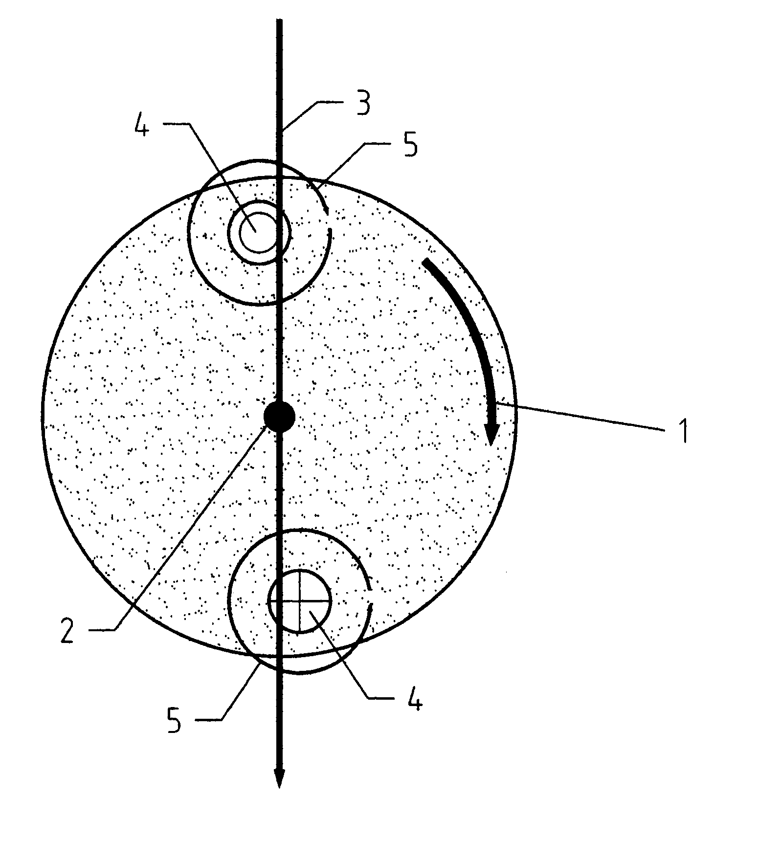
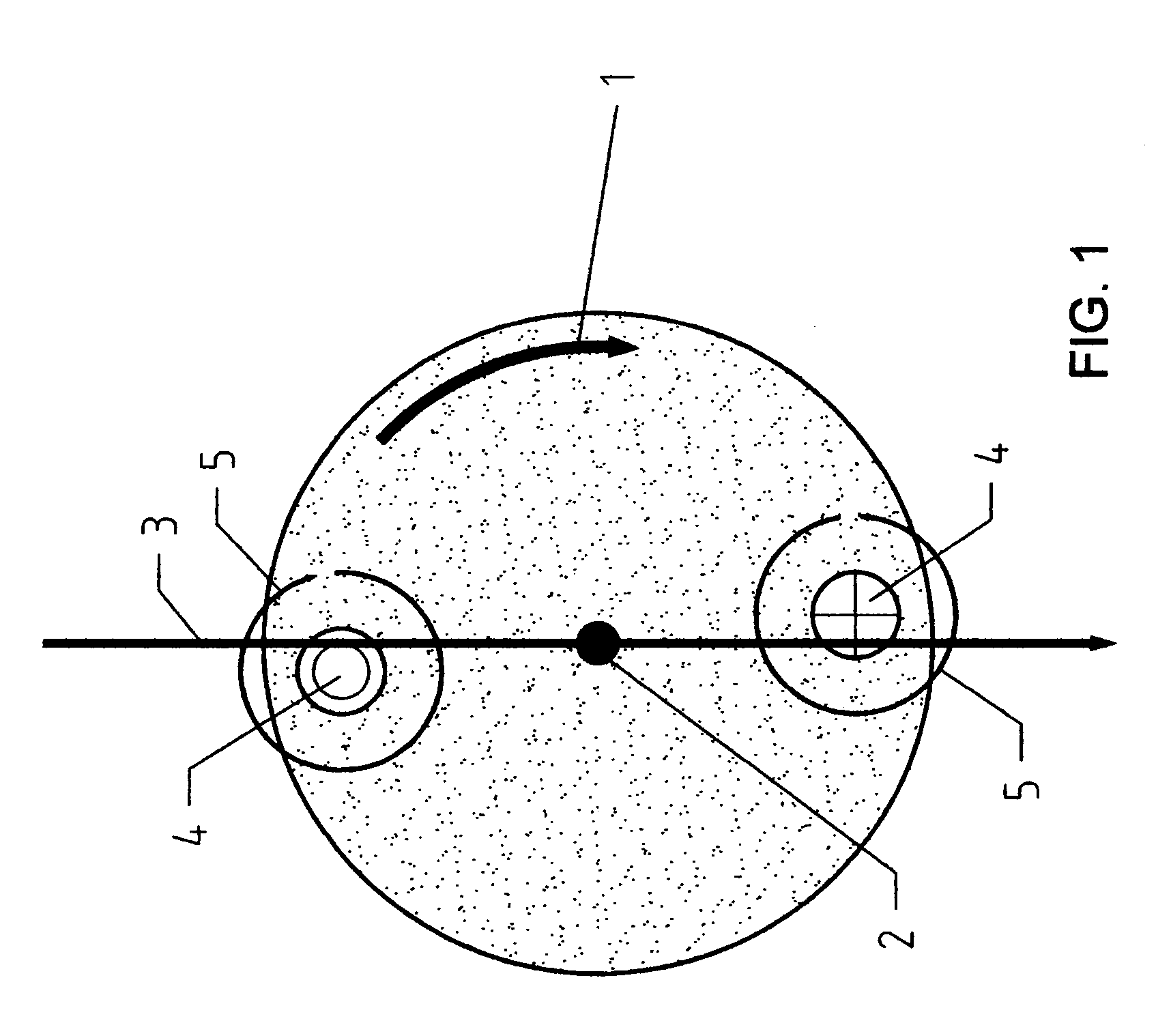
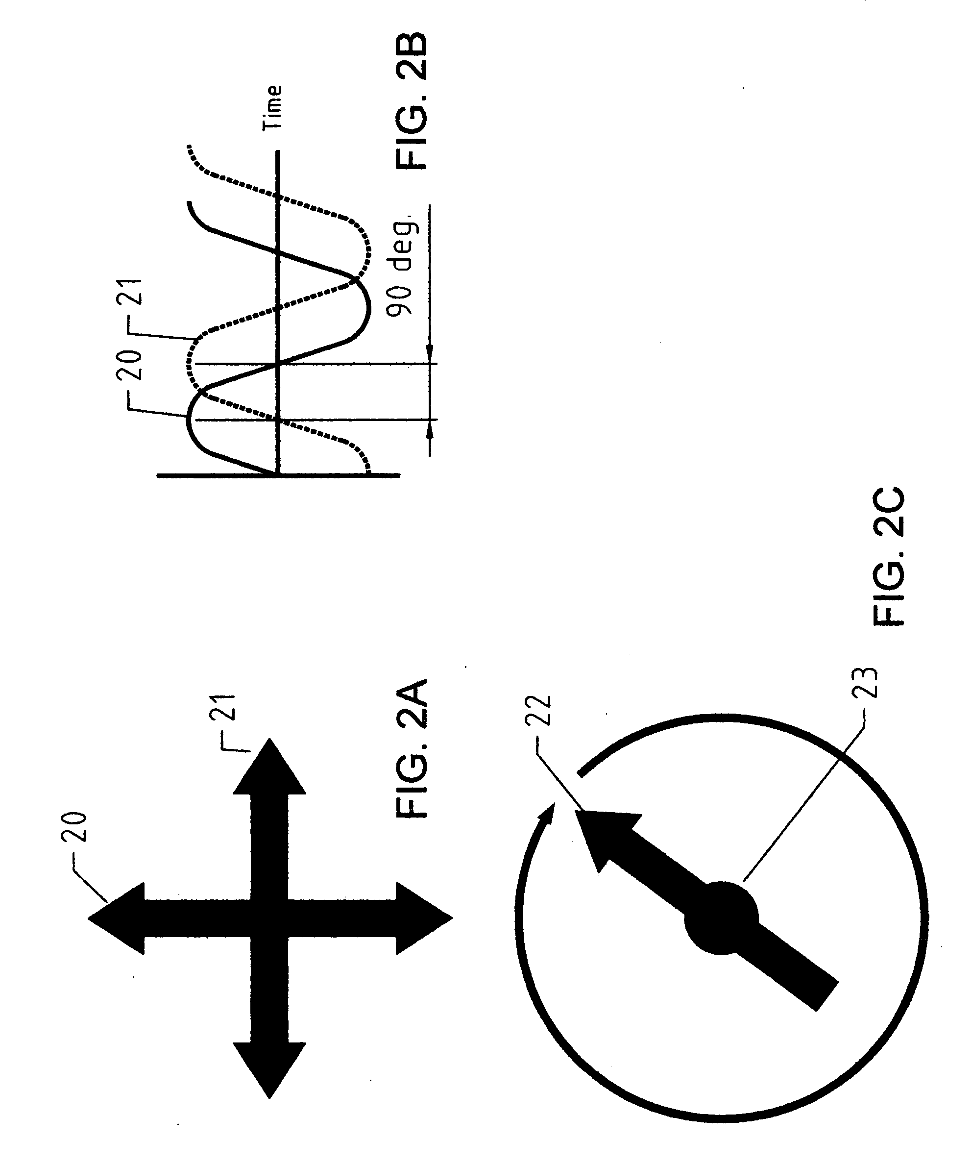
[0012] The present invention is directed to a method for forming and sustaining a direct current loop in a plasma by an electromagnetic interaction. A polyphase rotating electromagnetic field causes at least a portion of the plasma to rotate about an axis perpendicular to the lines of an applied magnetic field passing through the plasma. The rotating conductive plasma moves across the applied field lines and generates B×V electromotive forces on the positive ions and electrons. The positive ions and electrons are moved in opposite directions to form a direct current loop that is stationary relative to the applied field and lies in a plane that includes the axis of rotation. I×B forces between the applied field and the generated current form a torque couple that slows the plasma rotation. This direct current loop formation process is analogous to motor-generator processes in rotating electrical machinery. The current loop creates its own poloidal field, and the self-interaction of the current loop with the poloidal field compresses the current-carrying plasma through the I×B pinch effect.

Problems solved by technology

Fusion power production is in the research and development stage, and has not reached commercialization.
These processes dissipate the plasma, and may damage structures.
For this reason, an objective in designing a magnetic containment system is to surround the plasma in a field with lines which form closed paths within the plasma confinement volume, and therefore do not provide direct escape paths along open field lines.
Such measures slow, but do not stop loss or neutralization of plasma.
While plasma discharges between metal electrodes are simple and permit both AC and DC currents, they have disadvantages.
In theory, the particles will orbit indefinitely, but in practice the orbits decay because of various losses.

Method used


Image

  • Rotating plasma current drive
  • Rotating plasma current drive
  • Rotating plasma current drive

Examples


Embodiment Construction

[0021] Upon examination of the following detailed description the novel features of the present invention will become apparent to those of ordinary skill in the art or can be learned by practice of the present invention. It should be understood that the detailed description of the invention and the specific examples presented, while indicating certain embodiments of the present invention, are provided for illustration purposes only. Various changes and modifications within the spirit and scope of the invention will become apparent to those of ordinary skill in the art upon examination of the following detailed description of the invention and claims that follow.

[0022] The present invention relates to devices that heat and confine plasma within sustained direct current electrical discharges and methods related to establishing and sustaining such discharges. More particularly the invention relates to forming such discharges by electromagnetic processes without electrodes. The inventi...


PUM


Abstract

The present invention includes electromagnetic methods and apparatus to form a sustained direct current loop in a conductive fluid such as plasma for applications including gas discharge arc lamps and fusion confinement systems. The current loop is driven by rotating plasma within a stationary magnetic field perpendicular to the axis of rotation. Polyphase rotating electric or magnetic fields drive the plasma rotation, and the interaction between the rotating plasma and the stationary field forms and sustains the current loop. Plasma cooling and contamination are minimized since, unlike conventional direct current drive methods and apparatus, no electrodes contact the plasma.

Description

CROSS-REFERENCE TO RELATED APPLICATION [0001] This application claims the benefit of an earlier filed provisional application 60 / 564,253.FIELD OF THE INVENTION [0002] The present invention relates to current drive methods and apparatus to form a sustained direct current loop in a conductive fluid such as plasma for the purpose of confining and heating the plasma. BACKGROUND OF THE INVENTION [0003] Plasma is a state of matter in which electrons are removed from atomic nuclei to form free electrons and ions. Plasma is electrically conductive, since both the free electrons and ions can move independently to carry charge. The free electrons and ions may recombine and release energy as electromagnetic radiation, and will heat and chemically modify solids, liquids or gases. At very high temperatures (100 million degrees K), the atomic nuclei collide with sufficient force that certain species, e.g. deuterium and tritium, fuse and release large quantities of energy. Plasmas therefore have a...

Claims


Application Information

Patent Timeline
IPC IPC(8): G21B1/00G21B1/05H05H1/46
CPCG21B1/05Y02E30/126H05H1/46H01J37/3266Y02E30/10
Inventor MEACHAM, GEORGE BEVAN KIRBY
Owner MEACHAM GEORGE BEVAN KIRBY
Learn More