Calibration solution system for use in an automatic clinical analyzer

a technology of automatic clinical analysis and solution system, which is applied in the field of apparatus, can solve the problem of undesired short useful life of calibration solution

Inactive Publication Date: 2005-11-10
DADE BEHRING
View PDF24 Cites 54 Cited by
  • Summary
  • Abstract
  • Description
  • Claims
  • Application Information

AI Technical Summary

Benefits of technology

[0006] The object of the present invention is to provide a random access biochemical analyzer adapted to determine when and which calibration solutions need to be evaluated by the analyzer and to automatically perform calibration and quality control protocols and make adjustments as required to maintain the analyzer in a proper and accurate analyzing condition. A calibration solution vial supply system important to the present invention employs container shuttles adapted to remove calibration solution vials from a loading tray and to inventory said solution vials on board the biochemical analyzer in a calibration solution server. In addition, the analyzer is adapted to automatically penetrate the closure covering the opening of the calibration solution vials, aspirate an amount of solution and dispense said solution into a test cuvette, thereby eliminating the previous need for operator intervention. This system thus provides a random access calibration solution supply system with the flexibility to position a large number of different calibration solution containers at aspiration locations by moving calibration solution vials between a calibration solution vial loading tray, at least one calibration solution vial server, and at least one calibration solution aspiration location.

Problems solved by technology

Problematically, current procedures employed in the industry for calibrating an analyzer require an operator to retrieve vial containing the requisite calibration solutions from a refrigerated area, open the closed vial or the like, typically by unscrewing a cap or removing a stopper, aspirating a portion of the calibration solution, possibly preparing diluted solutions to provide a range of analyte concentrations, and dispensing some or all of several calibration solutions into a test cuvette.
In certain instances, calibration solutions have an undesirably short useful life time during which the solution remains stable and thus are supplied in a more stable powdered form rather than in a less stable liquid form.

Method used


Image

  • Calibration solution system for use in an automatic clinical analyzer
  • Calibration solution system for use in an automatic clinical analyzer
  • Calibration solution system for use in an automatic clinical analyzer

Examples


Embodiment Construction

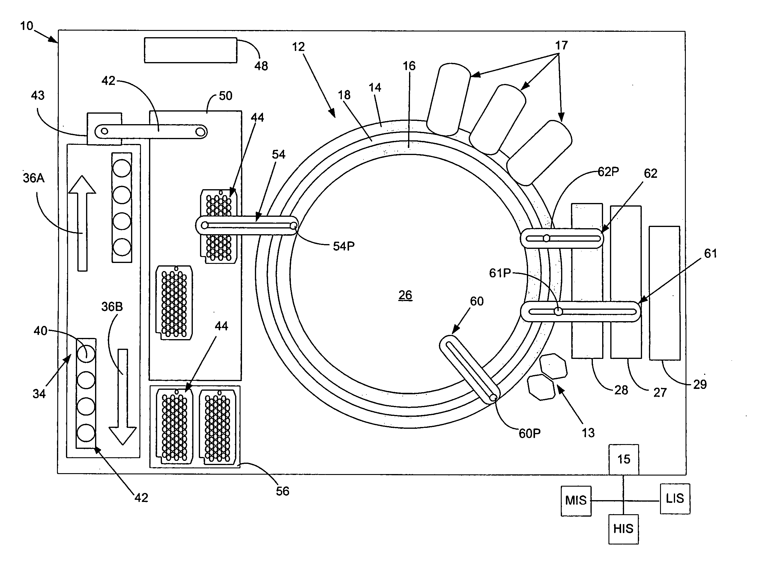
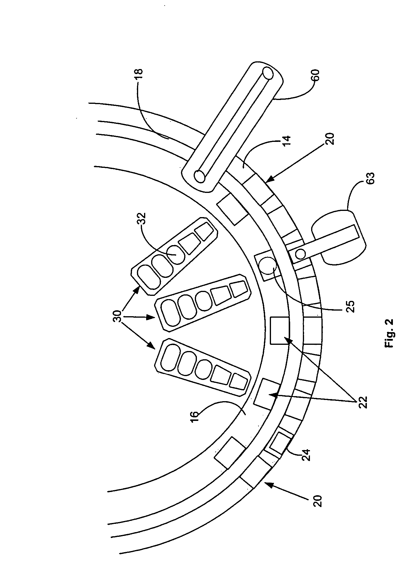
[0019]FIG. 1, taken with FIG. 2, shows schematically the elements of an automatic chemical analyzer 10 in which the present invention may be advantageously practiced, analyzer 10 comprising a reaction carousel 12 supporting an outer cuvette carousel 14 having cuvette ports 20 formed therein and an inner cuvette carousel 16 having vessel ports 22 formed therein, the outer cuvette carousel 14 and inner cuvette carousel 16 being separated by a open groove 18. Cuvette ports 20 are adapted to receive a plurality of reaction cuvettes 24 that contain various reagents and sample liquids for conventional clinical and immunoassay assays while vessel ports 22 are adapted to receive a plurality of reaction vessels 25 that contain specialized reagents for ultra-high sensitivity luminescent immunoassays. Reaction carousel 12 is rotatable using stepwise or cyclic movements in a constant direction, the movements being separated by a constant dwell time during which carousel 12 is maintained station...


PUM

PropertyMeasurementUnit
timeaaaaaaaaaa
concentrationaaaaaaaaaa
concentrationsaaaaaaaaaa

Abstract

A biochemical analyzer adapted to automatically perform calibration and quality control protocols using shuttles adapted to remove calibration and quality control solution vials from a loading tray and to inventory said solution vials on board the biochemical analyzer in a calibration and quality control solution server. In addition, the analyzer is adapted to automatically penetrate the closure covering the opening of the calibration and quality control solution vials, aspirate an amount of solution therefrom and dispense said solution into a test cuvette, thereby eliminating the previous need for operator intervention.

Description

FIELD OF THE INVENTION [0001] The present invention relates to an apparatus for automatically analyzing a patient's biological fluids such as urine, blood serum, plasma, cerebrospinal fluid and the like. More particularly, the present invention relates to a method for automating the processes involved in performing quality control procedures within an automated biochemical analyzer adapted for analyzing biological fluids. BACKGROUND OF THE INVENTION [0002] An increasing number of analytical assays related to patient diagnosis and therapy can be performed by automated biochemical analyzers using a sample of a patient's infections, bodily fluids or abscesses. Generally, such biochemical analyzers employ a combination of analyte specific chemical reagents and reaction monitoring means to assay or determine the presence or concentration of a specific substance or analyte within a liquid sample suspected of containing that particular analyte. Patient samples are typically placed in tube-...

Claims


Application Information

Patent Timeline
Patent Type & Authority Applications(United States)
IPC IPC(8): G01N35/00G01N35/02G01N35/04
CPCG01N35/00594G01N35/00712G01N2035/0458G01N35/026G01N35/025
Inventor DEVLIN, WILLIAM JACKSON SR.
Owner DADE BEHRING
Why Eureka
Try Eureka