
Method and apparatus for forming an optical element and substrate and moulding tool

Inactive Publication Date: 2005-11-10
SCHOTT AG
View PDF4 Cites 17 Cited by
  • Summary
  • Abstract
  • Description
  • Claims
  • Application Information

AI Technical Summary

Benefits of technology

[0012] It is an object of the present invention to provide a process and apparatus for forming an optical element by hot-forming, wherein inclusion of gas during the hot-forming process can be avoided more efficiently and wherein the optical element can be produced more precisely and cost efficient. According to another aspect of the present invention a substrate or glass preform for an optical element and a forming tool for forming the optical element using the process or apparatus according to the present invention is to be provided. According to another aspect of the present invention there is to be provided an optical element, produced with the novel method according to the present invention, and an optical imaging optics or optical engine having at least one such optical element.

Problems solved by technology

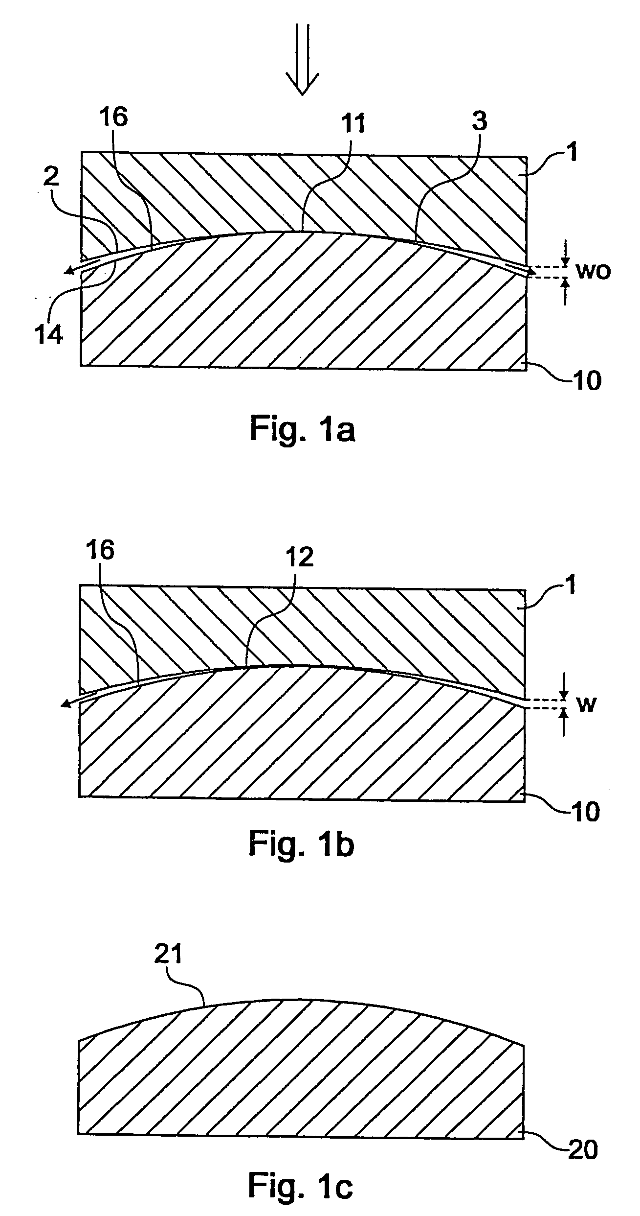
One problem when producing optical elements by hot-forming is the inclusion of process gases in the surface of the optical element during the hot-forming process, as this results in disturbing crater-shaped impressions on the surface of the optical elements.
This approach is, however, time-consuming and demanding for vacuum pumps.
However, the inclusion of process gas cannot be prevented reliably.
Furthermore, an additional molding tool and an additional process step are required, which is less efficient.
Furthermore, gas inclusions can hardly be predicted and modeled, so that it is very difficult to specify the precision of the optical elements to be produced in advance.
Even if the pressure is increased and decreased various times periodically, residual inclusions of process gas persist, which is detrimental to the surface quality of the optical element.
The material of the optical element is strongly deformed in this process, which results in relatively long processing times and high production costs.
If relative tiny structures are formed on the surface of the die, e.g. for forming microlenses or diffractive structures, the flow of the material into the structures, e.g. into impressions, cannot be controlled during the process.
Therefore one cannot prevent the inclusion of residual process gas into the surface of the optical element during the hot-forming process.
This results in a relatively long total processing time, which is not economical.
Furthermore, the relatively high deformation ratio of the preform requires relatively high process temperatures, which causes stress within the optical element after deformation.
It can occur that the softened or molten material of the preform adheres to the respective molding or hot-embossing portion at the relatively high process temperatures required, which is detrimental to the optical quality of the optical element.

Method used


Image

  • Method and apparatus for forming an optical element and substrate and moulding tool
  • Method and apparatus for forming an optical element and substrate and moulding tool
  • Method and apparatus for forming an optical element and substrate and moulding tool

Examples


embodiment 1

[0081] For pressing a planar array of cylindrical lenses (diameter 30 mm) with aspherical cylinder lenses, a glass preform having the same diameter, a planar surface and a convex surface with a radius of curvature of 300 mm is pressed. The convex surface faces the die with the array of cylinder lenses.

[0082] The heights of the cylinder lenses is 0.3 mm. Due to the curvature of the glass preform an additional pressing distance of proximately 0.4 mm has to be passed. The hot-forming is performed under a nitrogen atmosphere for preventing corrosion of the forming tools.

[0083] It has been observed that the aspherical surfaces of the cylinder lenses could be formed without any roughness due to inclusion of nitrogen.

embodiment 2

[0084] For pressing an aspherical imaging lens a glass preform having the same diameter (70 mm), a planar surface and a convex surface with a radius of curvature of 45 mm is pressed. The convex side faces the die with the array of cylinder lenses. Due to the curvature of the glass preform an additional pressing distance of approximately 0.3 mm has to be passed. It has been observed that aspherical surfaces could be formed without any roughness due to inclusion of nitrogen. Generally, the height of the structures is given by: z⁡(r)=cr21+1-(1+k)⁢c2⁢r2+α1⁢r2+α2⁢r4+…⁢ ⁢αn⁢r2⁢n

wherein:

[0085] Z: height of lens,

[0086] C: curvature,

[0087] K: conical parameter.

[0088] In the embodiment the parameters were chosen as follows:

[0089] c=1 / 36.409;

[0090] k=−1;

[0091] a2=1.08E-06

[0092] a4=2.16E-10

[0093] a6=−5.19E-15

wherein B270 was used as glass.

embodiment 3

[0094] For molding diffractive optical elements (DOE) on an aspherical imaging lens, an aspherical lens (designed according to embodiment 2) was used. The planar surface was coated with plastic material and subsequently structured by a DOE form using a molding process as described above. The planar surface faced the die with the DOE. Due to the curvature of the glass preform, an additional molding distance of approximately 0.05 mm had to be passed. It has been observed that DOEs without any roughness due to inclusion of nitrogen could be produced. The phase function of the DOEs is given by:

φ(r)=−6.75r2+0.001045r4

wherein f[rad] and r: 0-35 mm.

[0095] Referring to FIG. 9 in the following an exemplary imaging optics comprising at least one optical element produced according to the present invention will be described. Referring to FIG. 9, the imaging optics comprises three optical lenses disposed one behind the other, wherein the first lens is a convex-convex lens having a radius of c...


PUM

PropertyMeasurementUnit
Temperatureaaaaaaaaaa
Pressureaaaaaaaaaa
Structureaaaaaaaaaa

Abstract

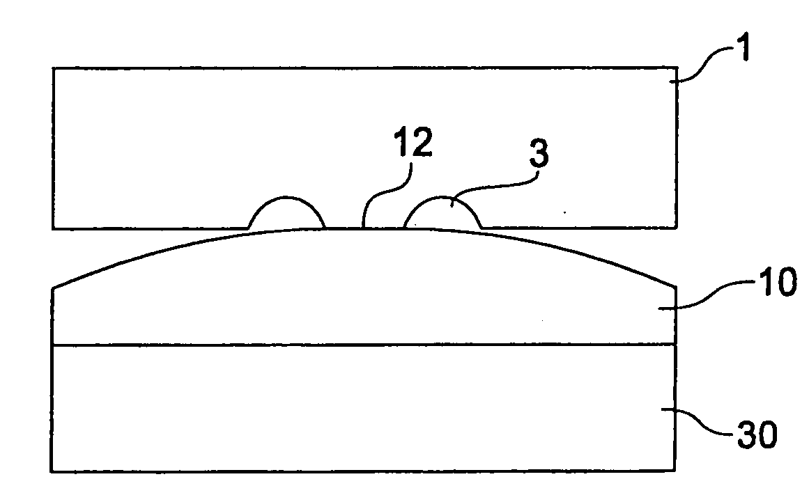
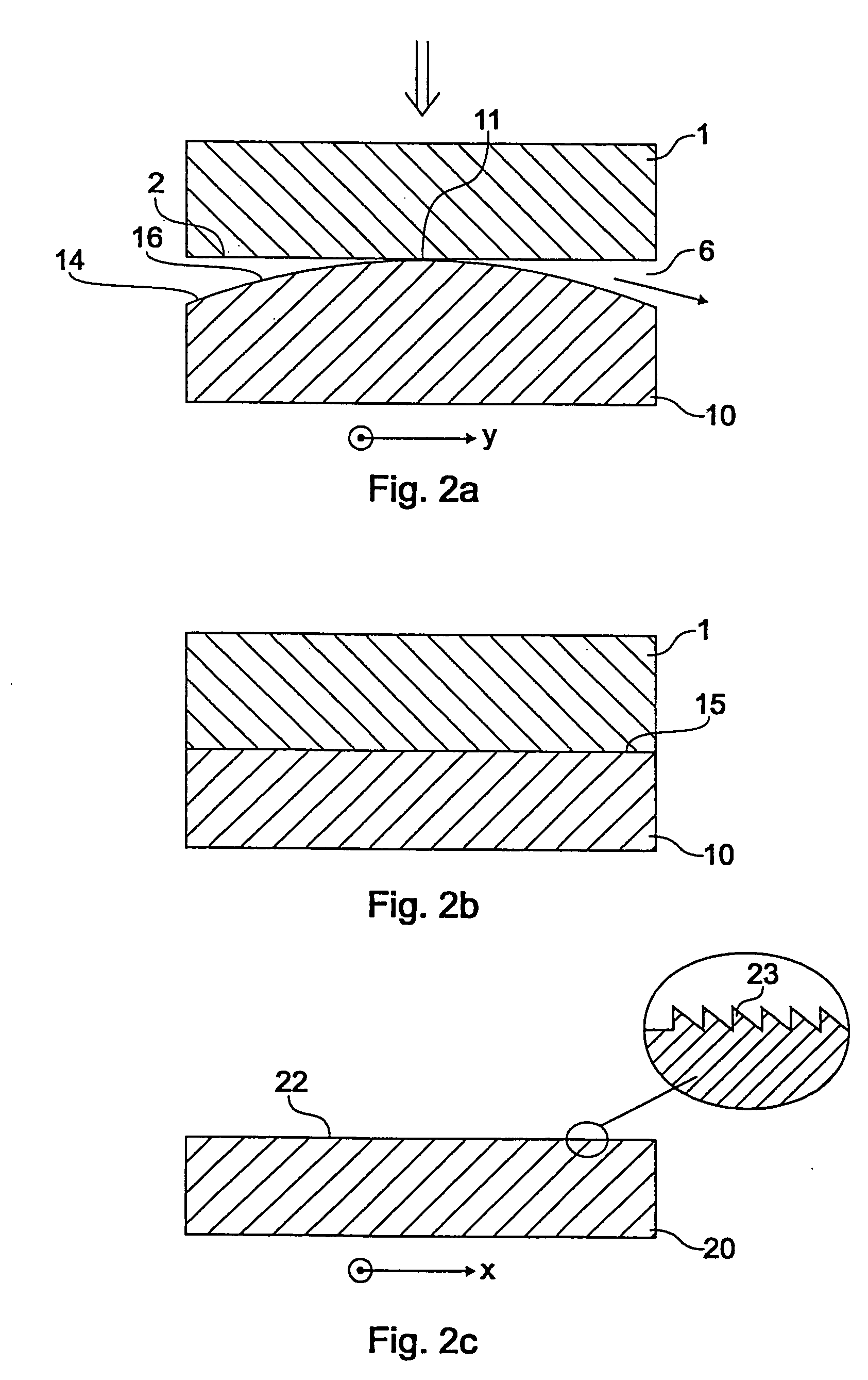
The invention relates to a process for forming an optical element. A forming tool is used having a plurality of molding or hot-embossing portions formed on a surface thereof for molding or hot-embossing optical structures onto a substrate. On the surface of the substrate there is formed at least one preformed portion. The substrate is heated to a temperature above a transition temperature and the forming tool and the substrate are pressed against each other for forming an optical element having a plurality of structures having an optical effect, wherein the shape of the structures having an optical effect is given by the respective associated molding or hot-embossing portion. According to the invention, when the forming tool and the substrate are pressed against each other, the respective preformed portion of the substrate first of all gets into contact to the associated molding or hot-embossing portion or to the forming tool at a central area so that a nip, which is formed between a surface of the respective preformed portion and a surface of the associated molding or hot-embossing portion or of said forming tool extends and broadens from said central area towards an edge of the respective preformed portion or of said substrate. According to the invention the substrate and said forming tool are provided with a substantially identical base so that the deformation ratio of the substrate is advantageously low.

Description

FIELD OF INVENTION [0001] The present invention relates in general to the production of optical elements by hot-forming of optical substrate, in particular by pressing or hot-embossing or molding an optical substrate. In particular, the present invention relates to a method for forming an optical element by a hot-forming process as well as to a substrate and a forming tool for such a method. BACKGROUND OF INVENTION [0002] Diffractive optical elements (DOEs), lens arrays and refractive microoptical elements are becoming more and more important as elements of modern optics. Many electronic devices for consumer market applications nowadays often include also optical elements that are decisive for a key function of the electronic devices. As an example, mobile telephones with integrated digital cameras are becoming more and more popular nowadays. Also in optical recording apparatus optical elements for precise imaging and forming of light rays during reading and / or writing are necessary...

Claims


Application Information

Patent Timeline
IPC IPC(8): B29C43/02B29D11/00G02B3/00C03B11/00C03B11/08G02B3/02G02B5/18
CPCB29C43/021B29D11/00B29D11/00317B29D11/00365B29D11/00769B29L2011/0016Y10T428/24479C03B11/082C03B2215/41C03B2215/412C03B2215/65G02B5/18Y10S425/808C03B11/08G07F13/06G07F9/10
Inventor WOLFING, BERNDPAWLOWSKI, EDGARSTOHR, ULRIKEBIERTUMPFEL, RALF
Owner SCHOTT AG
Learn More