Microinjection device and microinjection method

Inactive Publication Date: 2005-11-10
FUJITSU LTD
View PDF5 Cites 17 Cited by
  • Summary
  • Abstract
  • Description
  • Claims
  • Application Information

AI Technical Summary

Benefits of technology

[0017] It is an object of the present invention to solv

Problems solved by technology

However, the electrical method causes severe damage to the cells, the chemical method has poor efficiency, the biological method has a defect that not all the materials can be introduced in the cells.
When the culture fluid is adsorbed, the culture fluid flows through the holes, however, the cells that flow along with the culture liquid can not pass through the holes and therefore get trapped in the holes due to the suction force.
However, due to various reasons the position of the needle cannot be controlled so accurately.
In addition,

Method used


Image

  • Microinjection device and microinjection method
  • Microinjection device and microinjection method
  • Microinjection device and microinjection method

Examples


first embodiment

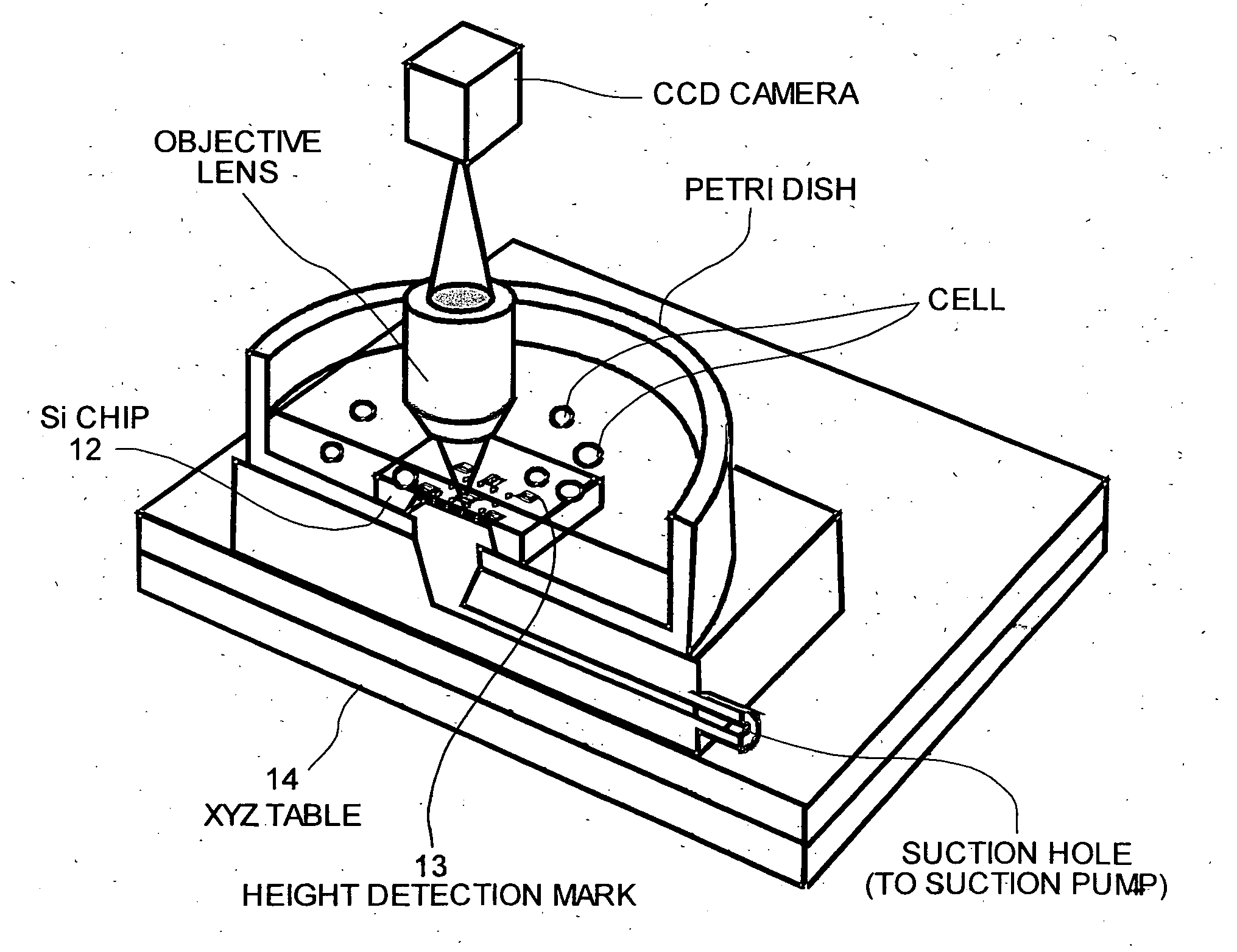
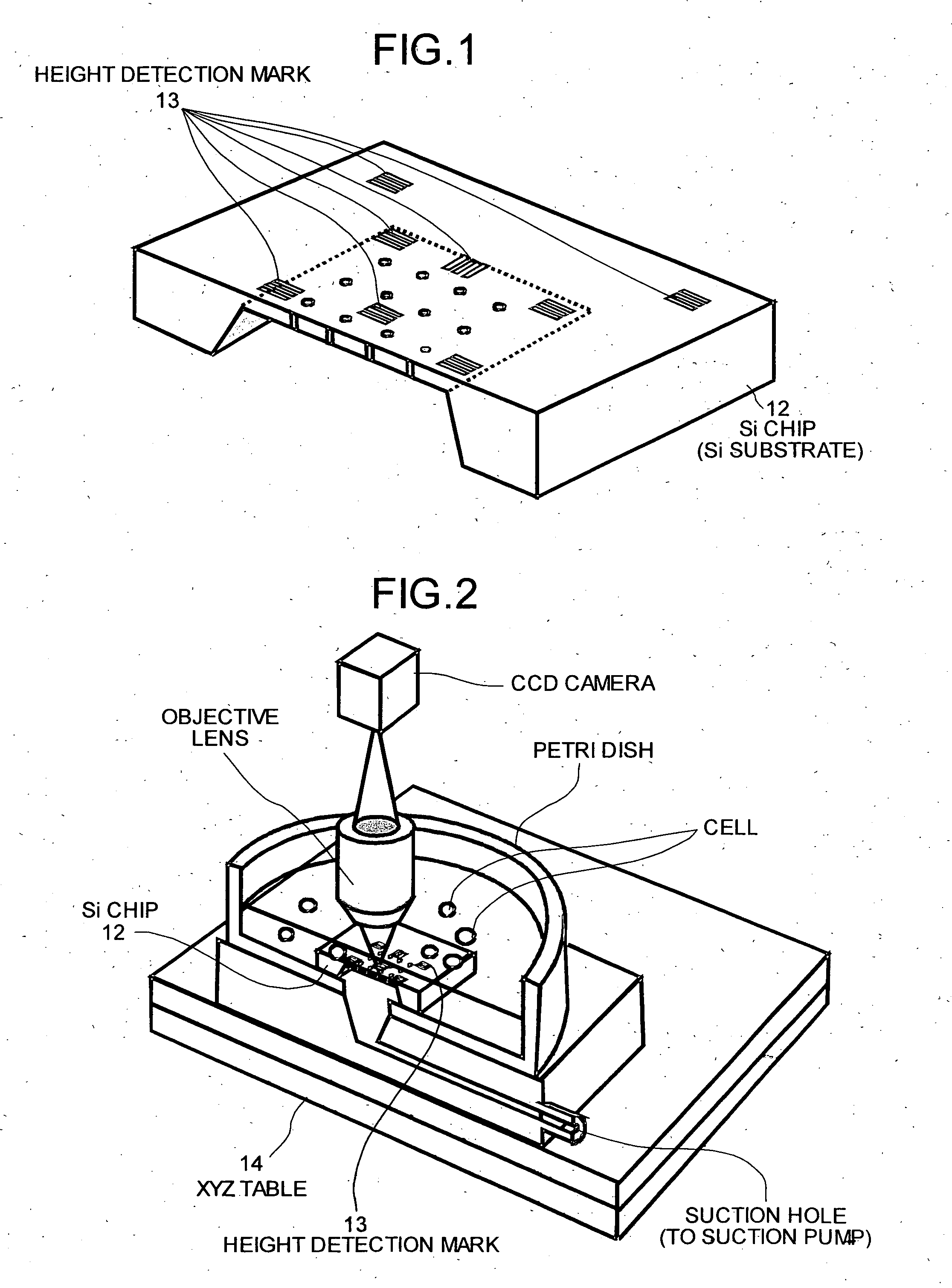
[0061] First, a microinjection apparatus that adjusts the position of the needle with respect to fluctuation of the height of the substrate is explained. FIG. 1 is a perspective of a Si chip (Si substrate) used in a microinjection apparatus according to a An Si chip (Si substrate) 12 is provided with a plurality of height detection marks 13 and these height detection marks 13 are used for adjusting the needle position with respect to the fluctuation of the height of the substrate.

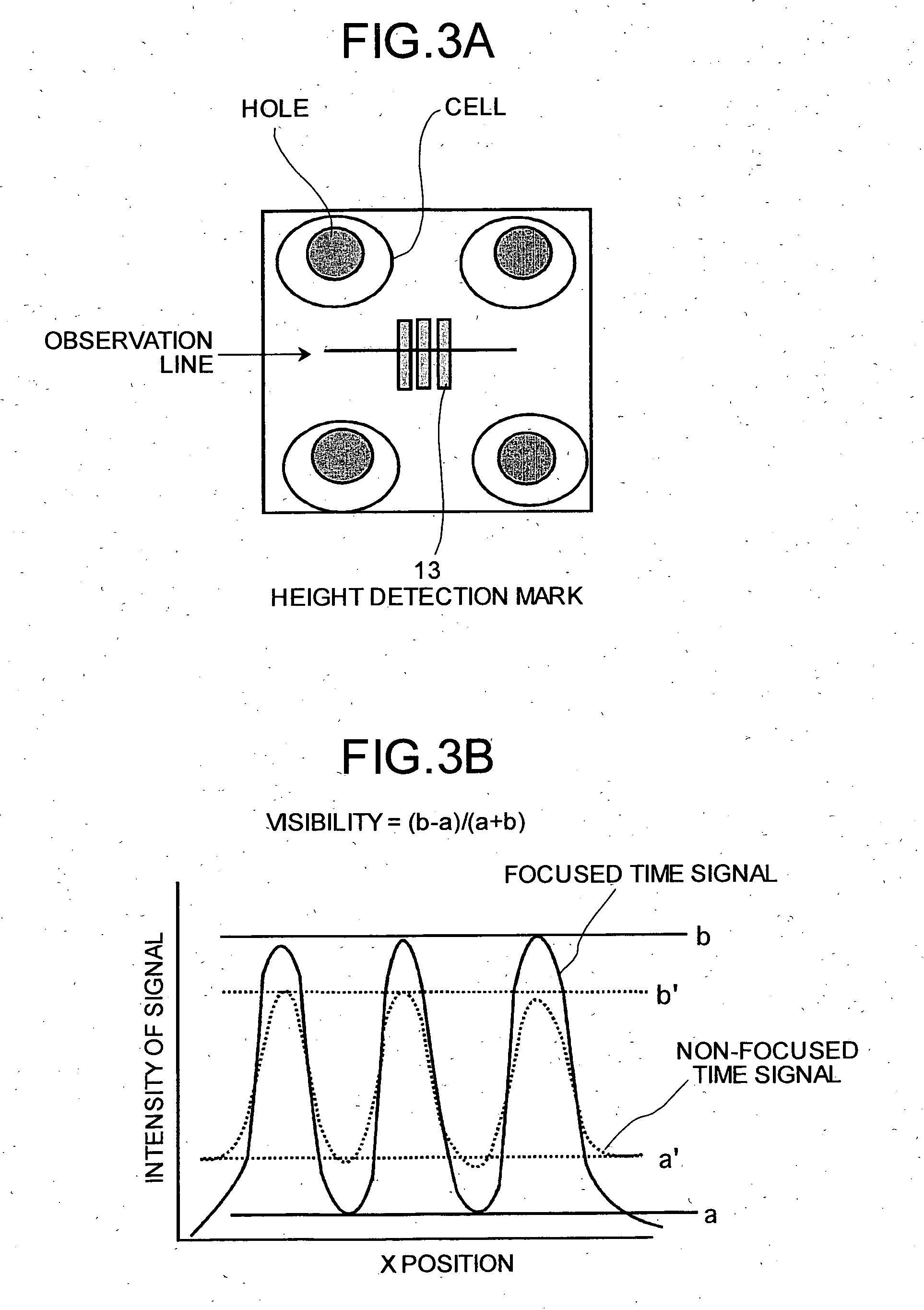
[0062] As shown in FIG. 1, each height detection mark 13 includes a pattern made of a plurality of fine lines. These lines are parallel to the surface of the Si chip. The height detection marks 13 are formed at various positions. For example, the height detection marks 13 are formed in the center and the periphery of the region where holes are formed, and even in regions where no holes are formed.

[0063] The microinjection apparatus according to the first embodiment can measure the posture of the Si chip a...

second embodiment

[0072] A microinjection apparatus is configured so as to adjust the height of the injection needle 11 along with the movement in the horizontal direction of the XYZ table 14. First, the necessity of adjusting the height of the injection needle 11 is explained.

[0073]FIG. 5 is a schematic for explaining the necessity of adjustment of the height of the injection needle 11. As shown in FIG. 5, the XYZ table 14 is generally not perfectly horizontal. Since the injection needle 11 projects toward the center of the cell, the distance between the tip of the injection needle 11 and the surface of the Si chip is only about 5 μm. Therefore, when the XYZ table 14 moves in the horizontal direction, injection to the cell that is trapped on the Si chip 12 becomes impossible. Further, in some cases the injection needle 11 may collide with the Si chip 12 thereby causing damage.

[0074] When there are a large number of holes in the Si chip, the holes occupy a wider area on the Si chip, resulting in an...

third embodiment

[0084] A microinjection apparatus according to the present invention if configured so as to adjust the position of the needle based on the fluctuation in position of the injection needle tip. First, the fluctuation in position of the injection needle tip is explained. FIG. 9 is a perspective for explaining the fluctuation in the position of the tip of the injection needle.

[0085] As shown in FIG. 9, the injection needle 11 may fluctuate in a horizontal plane in the x- and y-directions and make the injection impossible. The injection needle 11 can fluctuate due to deformation of a needle holding mechanism or deformation of the needle itself due to a change in surrounding temperature. Due to structural peculiarities of the needle, it fluctuates more in the y-direction than in the x-direction.

[0086]FIG. 10 is a schematic for explaining the problems caused due to the fluctuation of the injection needle 11. Not all the cells are absorbed in the hole, i.e., some cells may exist in a porti...


PUM

PropertyMeasurementUnit
Fractionaaaaaaaaaa
Forceaaaaaaaaaa
Diameteraaaaaaaaaa

Abstract

A microinjection apparatus includes a substrate having holes for trapping cells using suction force and injecting a substance into the cells with a needle. Height detection marks are provided on the substrate. A visibility is calculated from an image of a height detection mark, and an amount of deformation of the substrate is determined from the visibility. An XYZ table, on which the substrate is placed, is moved based on the amount of deformation.

Description

BACKGROUND OF THE INVENTION [0001] 1) Field of the Invention [0002] The present invention relates to a technology for trapping a cell in a hole and injecting a substance into the cells with a needle. [0003] 2) Description of the Related Art [0004] In recent years, studies on the modification of characteristics of a cell by injecting a gene into the cell as a method for the therapy of diseases due to genetic causes have been in progress. With such studies, roles of genes can be made clear and tailor made medicines that perform gene therapy suited for genetic characteristics of an individual can be prescribed. [0005] A gene can be injected into a cell with various methods that include an electrical method (electropolation), a chemical method (lipofection), a biological method (vector method), a mechanical method (microinjection), and an optical method (laser injection). [0006] However, the electrical method causes severe damage to the cells, the chemical method has poor efficiency, th...

Claims


Application Information

Patent Timeline
IPC IPC(8): C12M1/00C12N15/09C12M3/00C12N5/10
CPCC12M35/00
Inventor ANDO, MORITOSHISAKAI, SATORUSUTOU, YOSHINORI
Owner FUJITSU LTD
Why Eureka
Try Eureka