Gas detection device

a gas detection device and gas detection technology, applied in the direction of instruments, specific gravity measurement, mechanical means, etc., can solve the problems of unattainable accurate measurement, inability to identify odors widely floating in the environment, and inability to change the quality of sensor materials, etc., to achieve accurate measurement of test gas

Inactive Publication Date: 2005-11-17
SONY CORP
View PDF5 Cites 33 Cited by
  • Summary
  • Abstract
  • Description
  • Claims
  • Application Information

AI Technical Summary

Benefits of technology

[0021] According to the second gas detector of the present invention, the reference gas from the source of supply of the reference gas or the test gas from outside the enclosure is introduced into the sensor by reciprocating motion of the piston of the cylinder mechanism. Accordingly, an ambient gas can be measured by taking in the ambient gas from outside the enclosure as the test gas, and further, the test gas and the reference gas from the source of s...

Problems solved by technology

However, with repetition of the measurement, the odorous component attaches sensor 34 and hence the zero level of sensor 34 gradually changes from its initial state and an accurate measurement becomes unattainable.
However, when sensor materials adsorbing odor molecules are used, it is unavoidable that the odor molecules remain on the surface of the sensor material or that a highly active molecule contained in the gas combines with the sensor material to thereby cause the quality of the sensor material to be changed.
However, when an odor widely floating in the atmosphere surrounding the odor identifier is to be identified, it is impossible to take in the zero gas from the surroundings, and hence there has been a problem that the odor widely floating in the environment cannot be identified.
However, this is not what aims at identification of an atmospheric odor.
It is configured to take in the test gas, as well as the zero gas, from a container connected to the apparatus and it is not designed to be portable for identifying an atmospheric odor.
Further, since the layout of the piping for making switchover between the zero gas and test gas is complicated an...

Method used


Image

  • Gas detection device
  • Gas detection device
  • Gas detection device

Examples


first embodiment

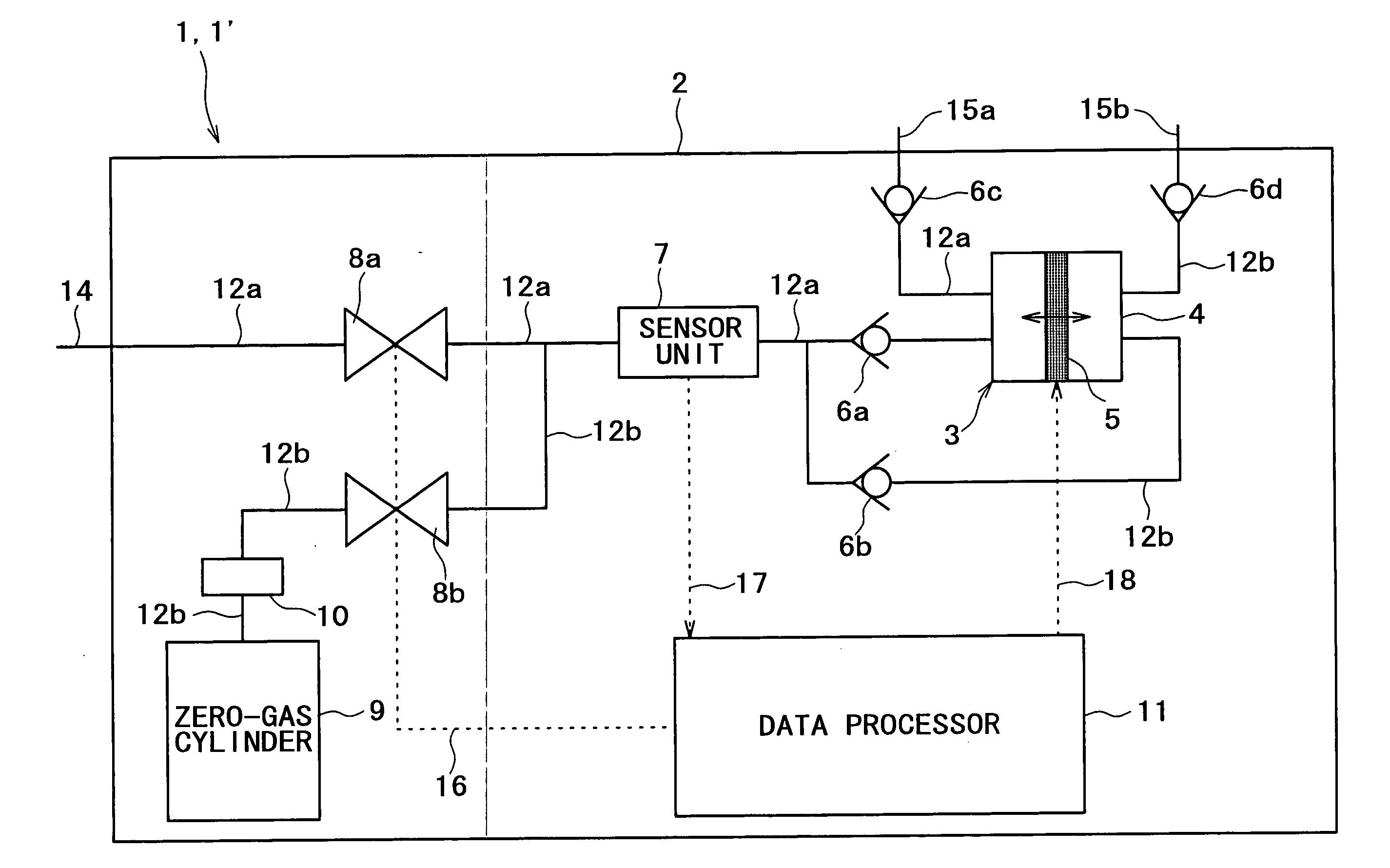
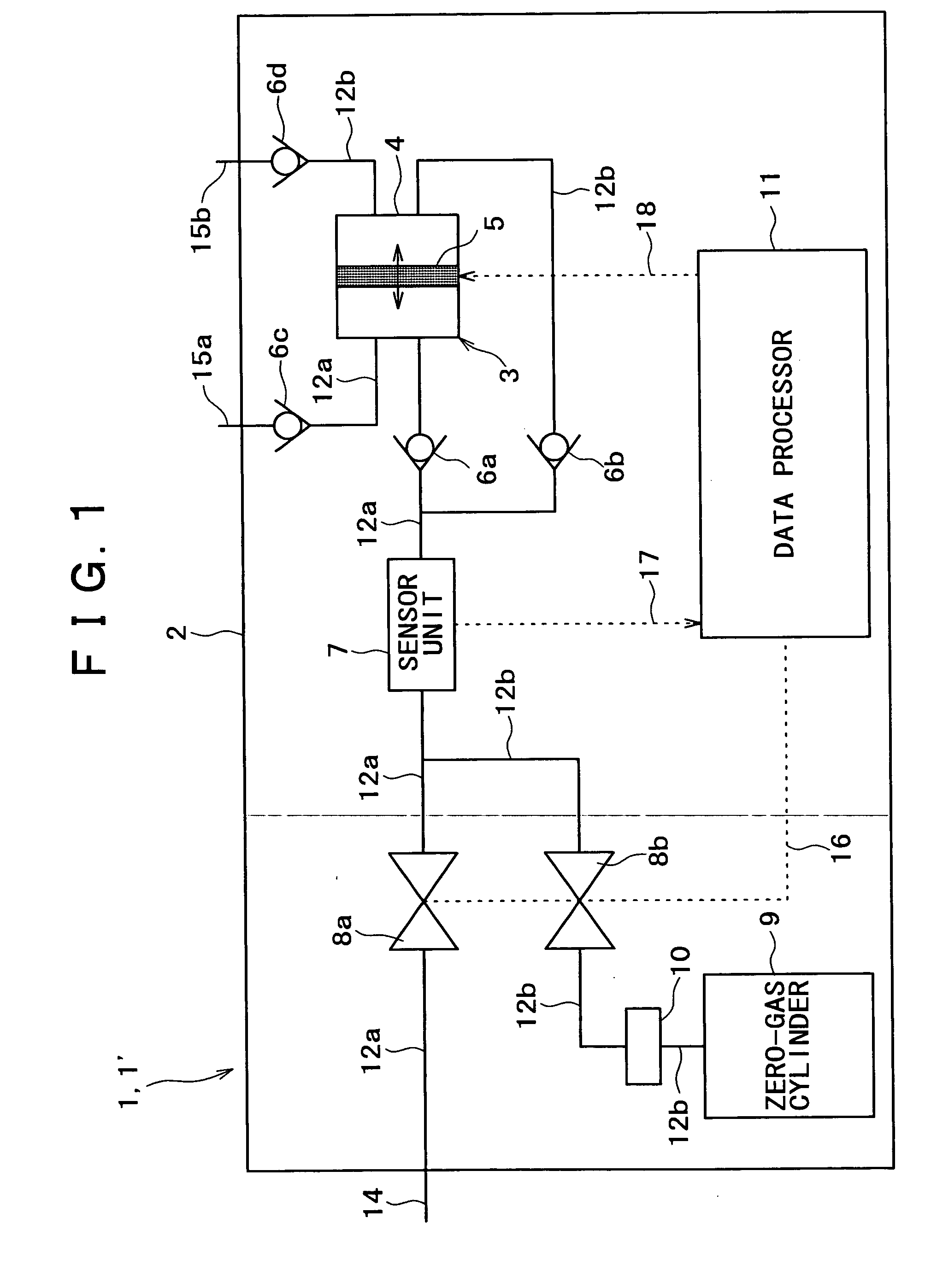
[0055] This gas detector is such that detects a particular component (odor) contained in a gas for testing (hereinafter, it may sometimes be called “test gas”), its quantity, its concentration, and others. The difference in the basic configuration between first gas detector 1 and second gas detector 1′ is that first gas detector 1 is specified by having the source of supply of a gas for reference (hereinafter, it may sometimes be called “zero gas”) installed in the enclosure and second gas detector 1′ is specified by having a cylinder mechanism provided as the gas intake / exhaust mechanism.

[0056] Accordingly, in the following description (including description of other embodiments to be described later), if there is made no remark as to whether it relates to the first or the second gas detector, the description is applicable to both thereof in common. Incidentally, the drawings in the following description will also be used as drawings applicable to both in common.

[0057] First gas ...

second embodiment

[0092]FIG. 9 shows a schematic block diagram of gas detector 1A according to the present embodiment.

[0093] This gas detector 1A, like the above-described first embodiment, is adapted such that an ambient gas is taken into the enclosure as the test gas. It is configured to be different from the first embodiment in the source of supply of the reference gas, the cylinder mechanism, and pipes and valves accessory thereto. Otherwise, it is configured the same as embodiment 1 and it functions equally to the first and second gas detectors in the first embodiment. Such designs are applicable to the above-described first and second gas detectors.

[0094] As the mechanism for intake / exhaust of gas, syringe 21 made up of cylinder 4a and piston 5a for taking in, or exhausting, gas on one and the same side is installed in enclosure 2. As the source of supply of the reference gas, it is arranged such that the test gas after use is purified in purifier 19 and turned into the reference gas.

[0095] ...


PUM


Abstract

A gas detector capable of accurately measuring particular components (odors or the like) contained in an ambient gas to be measured, being compact, and capable of being easily formed to be portable, or producing low noise and capable of being small-sized. Having zero gas cylinder (9) as a supplying unit of a zero gas and component parts disposed within its enclosure (2) and using syringe (3) as a gas intake/exhaust unit, it alternately introduces a test gas, i.e., an ambient gas taken in from outside enclosure (2) through piping (12a), and the zero gas supplied from zero gas cylinder (9) into sensor unit (7) and measures the test gas, while having operation of each unit controlled by data processor (11). Thus, accurate measurement of the test gas is achieved by relatively comparing results of measurement on the gases at each measurement. In addition, gas detector (1) can be moved to a spot where measurement is to be made to have the test gas there measured. Further, by use of a cylinder mechanism producing low noise, the detector can quantify gas intake/exhaust and can be made small in size.

Description

TECHNICAL FIELD [0001] The present invention relates to a portable gas detector capable of detecting a particular component in an atmosphere and identifying, for example, an odor. BACKGROUND ART [0002]FIG. 14 is a block diagram of a conventional odor identifier 31. In FIG. 14, gas in the atmosphere is taken in through intake port 36, allowed to flow through sensor 34 installed in the path of piping 38, sent to exhaust pole 37 by pump 33 to be returned to the original atmosphere. At this time, an electric signal corresponding to the kind of the odor borne by the gas taken in is derived from sensor 34 and identification and concentration measurement of the odor are performed in data processor 35. [0003]FIG. 15 is a schematic outside view of conventional odor identifier 31 configured as described above. Within main body 32, there are incorporated sensor 34, data processor 35, pump 33, and the like shown in FIG. 14. An ambient gas taken in as zero gas (reference gas) 42 and test gas (ga...

Claims


Application Information

Patent Timeline
IPC IPC(8): G01N27/12G01N1/24G01N5/02G01N33/00
CPCG01N1/24G01N2001/247G01N33/0009
Inventor IMOTO, TSUTOMU
Owner SONY CORP
Why Eureka
Try Eureka