Multi-stage compression ignition engine start

a technology of compression ignition and engine start, which is applied in the direction of engine starters, electric control, machines/engines, etc., can solve the problems of poor idle stability, excessive white smoke, and particularly susceptible to cold start of compression ignition engines

Active Publication Date: 2005-11-17
ALLISON TRANSMISSION INC
View PDF2 Cites 171 Cited by
  • Summary
  • Abstract
  • Description
  • Claims
  • Application Information

AI Technical Summary

Benefits of technology

[0005] The present invention provides a method for starting a compression ignition engine. The compression ignition engine is operatively coupled to an electric machine which is effective to spin up the engine during cranking. The starting sequence includes cranking the engine with the electric machine up to a first speed that is below the natural resonant speed of the coupled engine and electric machine combination. First speed cranking is maintained for a first duration and thereafter the engine is cranked up to a second speed that is above the natural resonant speed of the engine and motor combination. The first speed cranking terminates when the engine demonstrates relative stability at the first speed. Similarly, the second speed cranking terminates when the engine demonstrates relative stability at the second speed. Subs...

Problems solved by technology

Compression ignition engines are particularly susceptible to cold-start issues such as slow start times, excessive white smoke exhaust due to misfiring cycles, oil starvation, and poor idle stability.
All of these make fuel evaporation difficult which in turn frustrates combustion.
Cold starting also means compromised battery voltage which reduces its electrical current capability.
Cold temperat...

Method used


Image

  • Multi-stage compression ignition engine start
  • Multi-stage compression ignition engine start
  • Multi-stage compression ignition engine start

Examples


Embodiment Construction

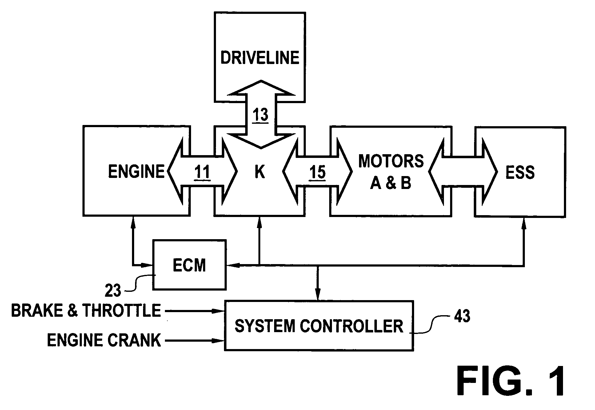
[0010] With reference first to FIG. 1, a block diagram of an exemplary dual-motor, electrically variable transmission powertrain to which the present invention is applicable is illustrated. The powertrain includes a diesel compression ignition engine, a vehicle driveline and a pair of electric motors. The motors (identified as A and B), driveline and engine are operatively coupled to one another, for example, through a coupling means (K) comprising one or more planetary gearsets and selective coupling paths established in accordance with application and release of various torque transfer devices, e.g., clutches. The engine is coupled (11) to the coupling means at a mechanical input thereof. The driveline is coupled (13) to the coupling means at a mechanical output thereof. The motors are coupled (15) to the coupling means at various rotating members of the planetary gearsets. Neglecting power losses, the power flows between the engine, driveline and motors balance. And, the power at...


PUM


Abstract

A powertrain includes a diesel compression engine and an electric machine operatively coupled thereto and effective to rotate the engine during engine cranking. Cold engine cranking is accomplished in a staged manner including a first stage wherein the engine is cranked to a first speed below the resonant speed of the coupled engine and electric machine combination for a first duration and thereafter cranked to a second speed above the resonant speed for a second duration. Transition out of cranking at the first and second speeds is accomplished when relative combustion stability is demonstrated. Cranking at the first or second speed is aborted when excessive crank times or if low battery voltages are observed. A third stage is included wherein the engine is cranked to a third speed below the engine idle speed. Transition out of cranking at the third speed is accomplished when relative combustion stability is demonstrated, whereafter normal engine control takes over.

Description

TECHNICAL FIELD [0001] This invention relates to compression ignition engines. More particularly, the invention is concerned with cold starting of such engines. BACKGROUND OF THE INVENTION [0002] Compression ignition engines are particularly susceptible to cold-start issues such as slow start times, excessive white smoke exhaust due to misfiring cycles, oil starvation, and poor idle stability. Cold starting means low temperature intake air that is coming inside the cylinder, low temperature walls, and low temperature piston heads. All of these make fuel evaporation difficult which in turn frustrates combustion. Cold starting also means compromised battery voltage which reduces its electrical current capability. The viscosity of oil increases dramatically with decreases in temperature, which results in increased frictional resistance during cold engine starts. The increased frictional drag is especially important when starting compression ignition engines because of the high minimum ...

Claims


Application Information

Patent Timeline
IPC IPC(8): F02D41/06F02N11/00F02N11/08F02N15/00F02N99/00
CPCF02D41/064F02N2300/102F02N11/08
Inventor SAH, JY-JEN F.HUBBARD, GREGORY A.CAWTHORNE, WILLIAM R.TAO, XUEFENG T.STEINMETZ, TODD M.
Owner ALLISON TRANSMISSION INC
Why Eureka
Try Eureka