Rail sleeper and ballast-free track structure

a track structure and rail sleeper technology, applied in the direction of track superstructure, railway track construction, ways, etc., can solve the problems of minor and fundamental improvement in the design and construction of conventional railway tracks, serious and persistent problems that have never been completely resolved, and the progressive degradation of track structures under repeated loading remains problematic, so as to facilitate rapid installation and replacement of railway tracks

Inactive Publication Date: 2005-11-17
HIGHFLYER INVESTMENTS & TRADING 6
View PDF1 Cites 13 Cited by
  • Summary
  • Abstract
  • Description
  • Claims
  • Application Information

AI Technical Summary

Benefits of technology

[0009] It is an object of the present invention to provide a rail sleeper suitable for use in erecting a railway track that will overcome or at

Problems solved by technology

However, for over a century there has been very little fundamental improvement in the design and construction of conventional, ballasted railway track.
Consequently, some serious and persistent problems have never been completely resolved.
In particular, the progressive degradation of the track structure under repeated loading remains problematic.
This degradation is manifest in several ways, including loss of geometric stability (the ballast spreads and settles, resulting in loss of vertical and horizontal alignment); loss of resilience (the ballast degrades and becomes contaminated by finer material resulting in increased dynamic damage to track structure (corrugations) as well as to rolling stock); and pumping of sub-grade (caused by dynamic loading, and resulting in ballast fouling and destruction of formation).
Th

Method used


Image

  • Rail sleeper and ballast-free track structure
  • Rail sleeper and ballast-free track structure
  • Rail sleeper and ballast-free track structure

Examples


Embodiment Construction

[0043] Without limiting the scope thereof, two embodiments of the invention will now be described by way of example only and with reference to the accompanying drawing wherein—

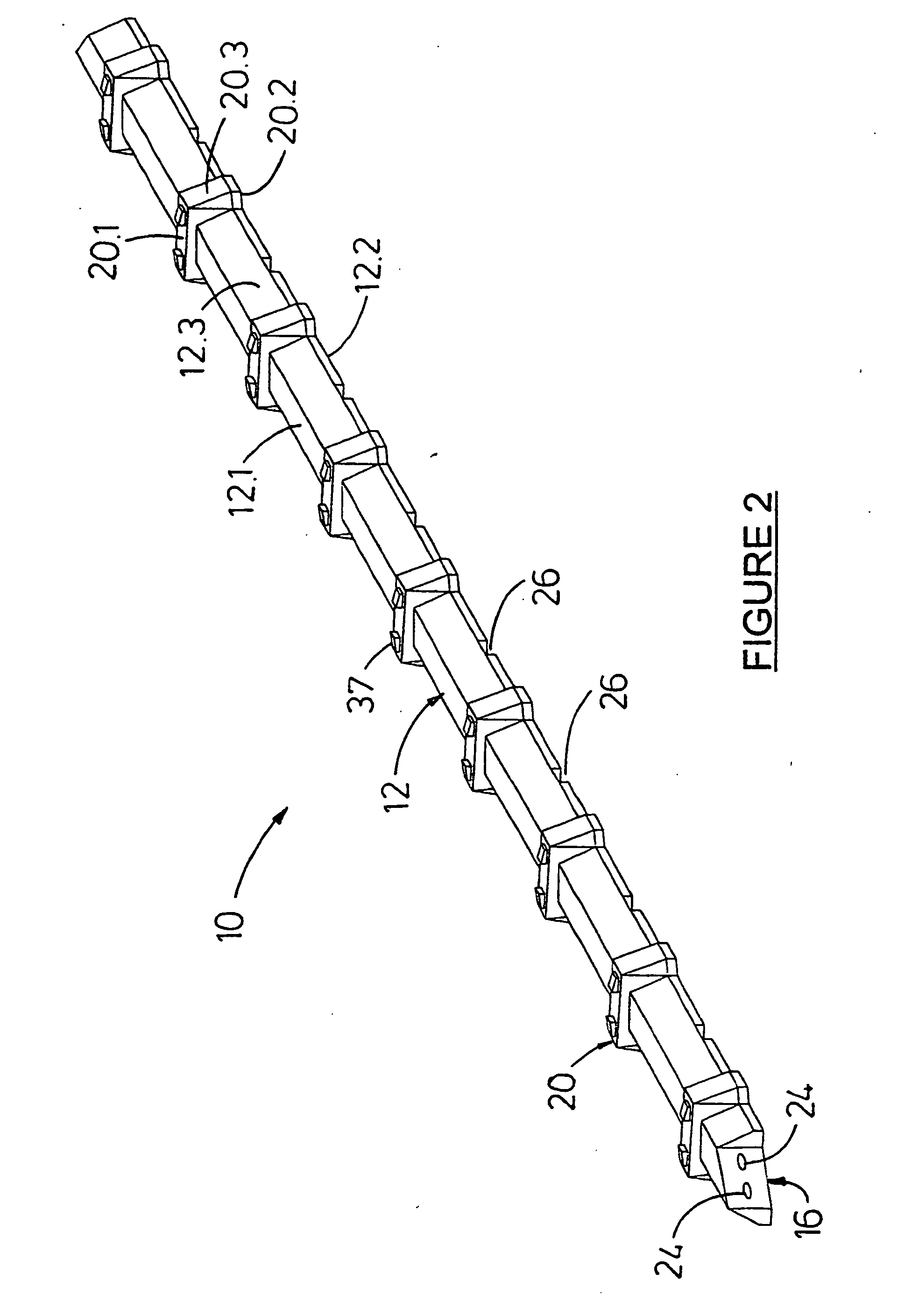
[0044]FIG. 1 is an isometric view of a rail sleeper according to one embodiment of the invention, wherein the rail sleeper is designed for light axle load applications such as underground mining;

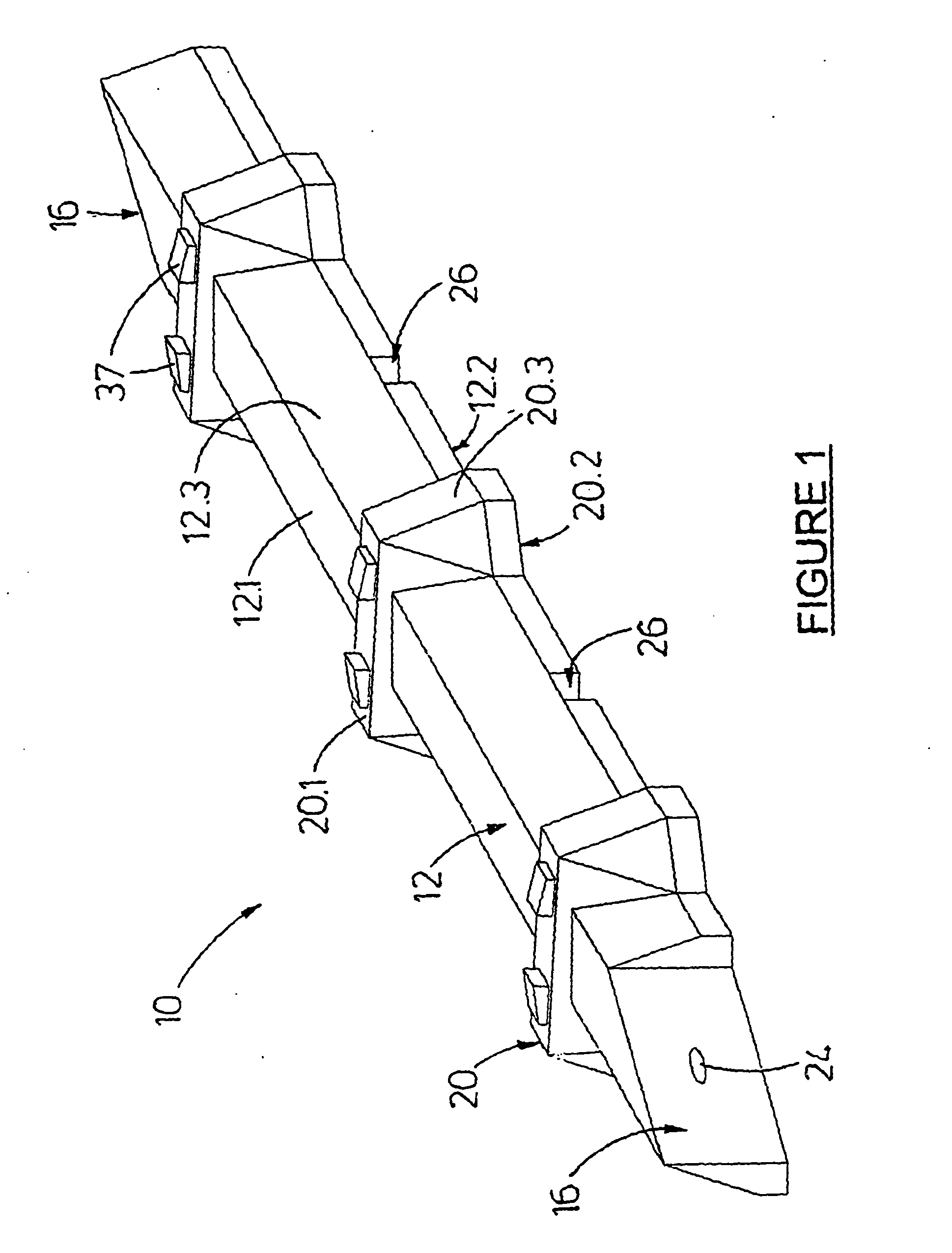
[0045]FIG. 2 is an isometric view of a rail sleeper according to another embodiment of the invention, wherein the rail sleeper is designed for heavier axle loads such as main line applications;

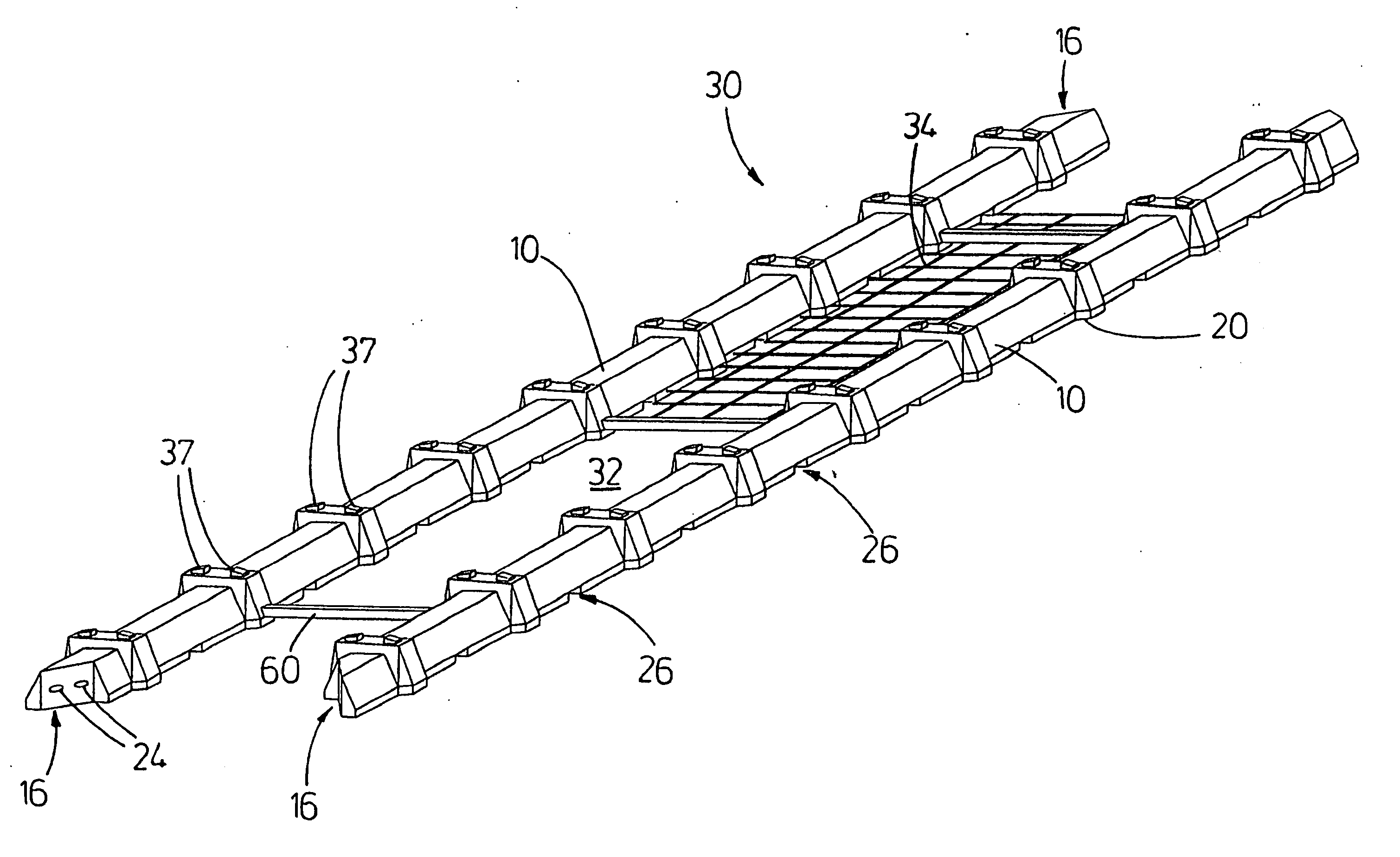
[0046]FIG. 3 is an isometric view of a track structure according to one embodiment of the invention;

[0047]FIG. 4 is an isometric view of a track structure according to another embodiment of the invention, including a wire mesh extending between the sleepers;

[0048]FIG. 5 is a transverse cross-sectional view of the track structure of FIG. 4;

[0049]FIG. 6 is a transverse cross-sectional view of a track structure according to the...


PUM


Abstract

According to one aspect of the invention there is provided a prefabricated rail sleeper [10] suitable for use in erecting a track structure [30]. The rail sleeper [10] comprises an elongate body portion [12] for supporting rails [14], the body portion [12] including a top surface [12,1], a bottom face [12.1] and at least two side faces [12.3], and terminating at least at one end thereof in a transition joint formation [16] dimensioned matingly to engage a complimentarily dimensioned transition joint formation [16] of an adjacent rail sleeper [10] in use so as to form a substantially continuous track structure. The sleeper [10] also includes a series of block formations [20], each of which is at least partially outwardly flared and extending beyond the side faces [12.3] of the body portion [12] so as to increase shear interlock of the sleeper [10] with the track bed to reduce longitudinal creep; as well as a series of transverse drainage ducts [26] extending underneath the rail sleeper [10] for allowing rainwater drainage between different side faces [12.3] of the body portion [12] and away from the rail sleeper. The invention extends to a ballast-free track structure [30] comprising at least two rail sleepers [10] according to the invention wherein the sleepers are located in spaced parallel orientation on a ballast-free track bed so as to define a centre drain [32] between the sleepers; and including a mesh [34] located between the sleepers [10] for reinforcing the centre drain [32].

Description

TECHNICAL FIELD [0001] This invention relates to a ballast-free track structure suitable for carrying railway rails, and to a rail sleeper for use in such a structure. BACKGROUND ART [0002] Conventional methods for laying a railway track involve placing large wooden, reinforced concrete or steel sleepers on a ballasted track bed, after which rails are fastened to the sleepers. The purpose of the ballast is to provide a free-draining foundation with high shear strength and good elastic (resilient) properties. [0003] However, for over a century there has been very little fundamental improvement in the design and construction of conventional, ballasted railway track. Consequently, some serious and persistent problems have never been completely resolved. In particular, the progressive degradation of the track structure under repeated loading remains problematic. This degradation is manifest in several ways, including loss of geometric stability (the ballast spreads and settles, resultin...

Claims


Application Information

Patent Timeline
IPC IPC(8): E01BE01B1/00E01B2/00E01B3/32E01B3/34
CPCE01B1/004E01B1/008E01B2/003E01B3/38E01B3/32E01B3/34E01B2/006
Inventor BRAITHWAITE, ERROL
Owner HIGHFLYER INVESTMENTS & TRADING 6
Why Eureka
Try Eureka