Electrical connecting method

Inactive Publication Date: 2005-11-17
SOCIONEXT INC
View PDF6 Cites 17 Cited by
  • Summary
  • Abstract
  • Description
  • Claims
  • Application Information

AI Technical Summary

Benefits of technology

[0034] There is a demand for a connecting method in which, when contact members and electrodes of an electronic part contact each other, a pressing force to be applied to both the contact members and the electrodes is reduced in order to minimize the damage to the electronic part and to the terminals of the e

Problems solved by technology

Therefore, the connecting method through soldering is hardly adapted to temporary connection that is performed in a case where, after an electronic part is tested or information is written in or read from the electronic part, the contact members are separated from the terminals of the electronic part.
Moreover, the surfaces of the contact member and the terminal have microscopic irregularities.
It is therefore hard to separate the sol

Method used


Image

  • Electrical connecting method
  • Electrical connecting method
  • Electrical connecting method

Examples


Example

First Embodiment

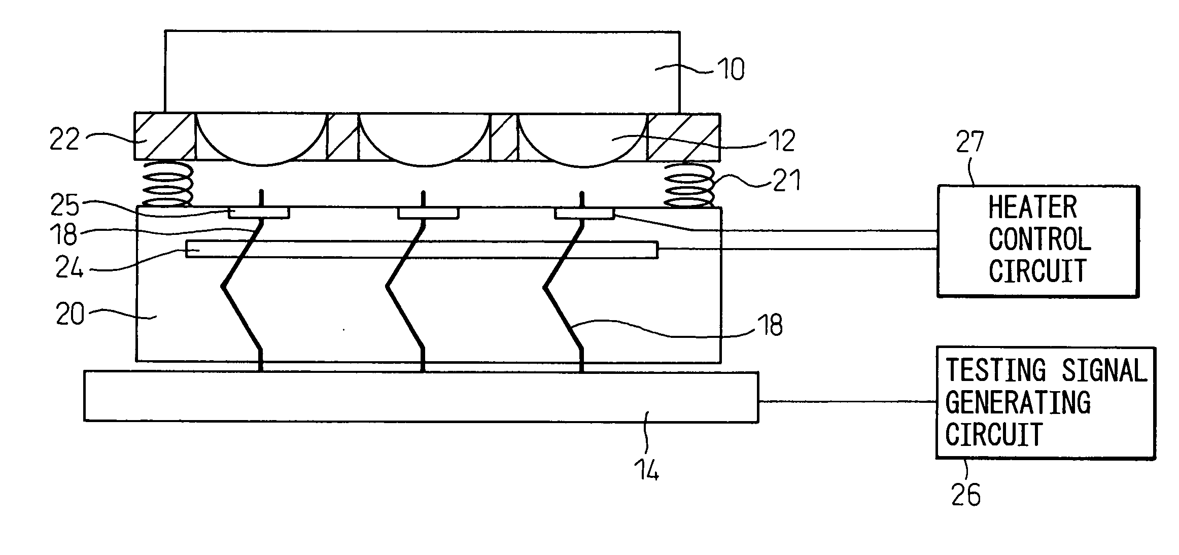
[0133] FIGS. 5 to 8 show an electronic part testing method to which the first embodiment of the present invention is adapted, the rough constitution of testing apparatus for carrying out the testing method, and a method of contacting the terminal of an electronic part to be tested with the testing terminal of the testing apparatus.

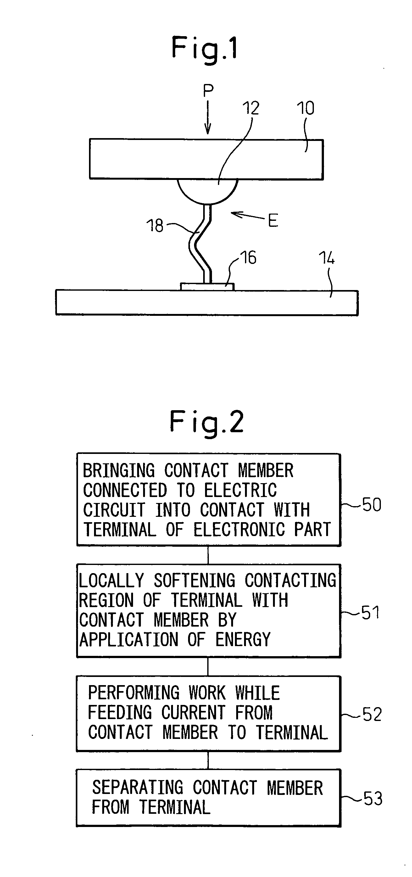
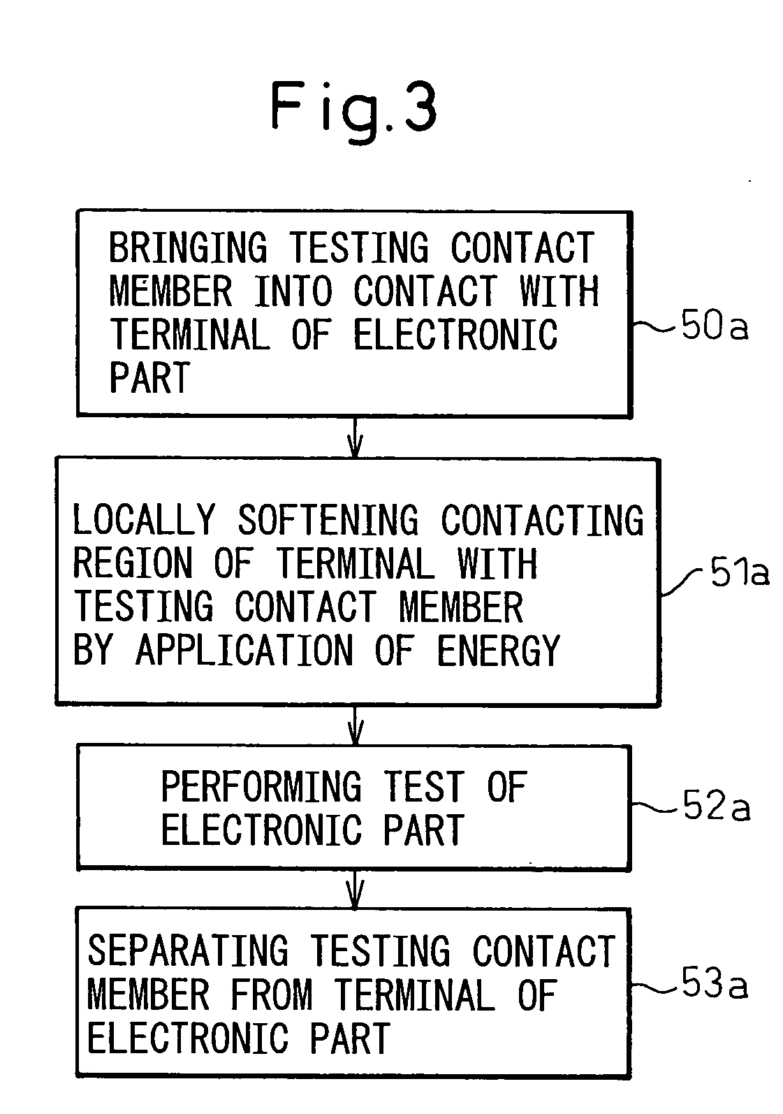
[0134]FIG. 9 is a flowchart illustrating the processing steps for carrying out the testing method and contacting method.

[0135] In FIG. 5, the electronic part 10 to be tested, such as an LSI chip has terminals 12.

[0136] On the other hand, the contact members 18 are held by a socket 20 and interposed between electrode pads (not shown) on the circuit board 14 and the terminal 12 of the electronic part 10.

[0137] A receptacle base 22 is elastically supported by the top of the socket 20 via a springs 21. The receptacle base 22 has openings 23 formed therein in register with the terminals 12 to receive the respective terminals 12 of the elect...

Example

Second Embodiment

[0157]FIG. 10 shows a method of contacting a testing contact member with a terminal of an electronic part, for carrying out an electronic part testing method according to the second embodiment of the present invention.

[0158]FIG. 11 is a flowchart illustrating the process steps for carrying out the testing method and the contacting method.

[0159] The arrangement of the testing apparatus shown in FIG. 10 has the similar configuration to the one employed in the first embodiment, except that this embodiment is different from the first embodiment in that means for applying energy to the contacting portion of the terminal of the electronic part and contact member.

[0160] In FIG. 10, the same reference numerals are assigned to components corresponding to those described in relation to the first embodiment.

[0161] In the second embodiment too, the contact member 18 connected to the electric circuit 14 is brought into contact with the terminal 12 of the electronic part 10....

Example

Third Embodiment

[0185]FIG. 15 shows an electronic part testing method according to the third embodiment of the present invention, and a method of contacting a terminal of an electronic part with a contact member for carrying out the testing method.

[0186]FIG. 16 is a flowchart illustrating the process steps for carrying out the testing method and the contacting method.

[0187] In the present embodiment, both heating using a heater employed in the first embodiment and heating with Joule heat employed in the second embodiment are adopted.

[0188] Consequently, the testing apparatus shown in FIG. 15 has the same configuration as those employed in the first and second embodiments.

[0189] In the present embodiment, after the electronic part 10 to be tested is placed in position and pressed (step 90 in FIG. 16), the terminal 12 is heated, by heating the contact member 18 using the heater 23 (step 91), and by Joule heat generated by flowing the current through the contact member 18a, the te...


PUM


Abstract

An electrical connecting method has the step of bringing a contact member connected to an electric circuit into contact with a terminal of an electronic part. A desired processing is performed by feeding current to the terminal via the contact member. The contact member is then separated from the terminal. When the contact member is brought into contact with the terminal, energy is applied to the contact member or the terminal in order to locally soften a portion of the terminal contacting the contact member. Thereafter, the desired processing is performed, in the state that the contacting portion of the terminal with the contact member is softened so as to reduce the contact resistance and so as to increase the subsequent separatability of the contact member from the terminal.

Description

BACKGROUND OF THE INVENTION [0001] 1. Field of the Invention [0002] The present invention relates to an electrical connecting method. [0003] 2. Description of the Related Art [0004] In a test of an electronic part having numerous fine terminals, such as an LSI wafer, an LSI chip, a chip-size package (CSP), or a semiconductor device, contact members (testing contact members) connected to an electric circuit included in a testing equipment are electrically connected to the terminals of the electronic part. Voltage is applied or current is fed to the terminals of the electronic part via the testing contact members whereby the electronic part is tested. [0005] Moreover, contact members connected to the electric circuit are electrically connected to terminals of an electronic part such as a semiconductor device having an information storage / preservation facility, whereby information is written in the electronic part or read therefrom. [0006] For connecting the terminal of an electronic p...

Claims


Application Information

Patent Timeline
IPC IPC(8): G01R1/073G01R31/26G01R31/02G01R31/28H01R33/76
CPCG01R31/2875G01R1/0735
Inventor MARUYAMA, SHIGEYUKINISHINO, TORU
Owner SOCIONEXT INC
Why Eureka
Try Eureka