Controller driver and display apparatus

a display device and control device technology, applied in the field of display devices, can solve the problems of etc., and achieve the effect of increasing power consumption and interconnection, increasing circuit size and power consumption

Active Publication Date: 2005-11-17
RENESAS ELECTRONICS CORP
View PDF6 Cites 49 Cited by
  • Summary
  • Abstract
  • Description
  • Claims
  • Application Information

AI Technical Summary

Benefits of technology

[0020] In case the configuration shown in FIG. 19 is applied to a controller driver (also termed a controller driver IC) of a display device of a mobile terminal, it becomes necessary to provide an image memory for storage of image data for a directly previous frame, apart from the display memory. The result is the increased size of the circuit, and increased power consumption and interconnections.
[0023] In case the memories for storing image data of two frames are provided in order to cope with over-drive driving, the circuit size and power consumption are increased and hence it becomes difficult to apply the controller driver to e.g. a mobile phone for which a demand is raised for reducing the size of the device and the power consumption.
[0031] According to the present invention, in a controller driver for comparing input image data and readout image data to effect over-drive driving, it is unnecessary to add a frame memory, thus enabling reduction in circuit size and power consumption and preventing the interconnections from being increased.

Problems solved by technology

The result is the increased size of the circuit, and increased power consumption and interconnections.
In case the memories for storing image data of two frames are provided in order to cope with over-drive driving, the circuit size and power consumption are increased and hence it becomes difficult to apply the controller driver to e.g. a mobile phone for which a demand is raised for reducing the size of the device and the power consumption.

Method used


Image

  • Controller driver and display apparatus
  • Controller driver and display apparatus
  • Controller driver and display apparatus

Examples


embodiment

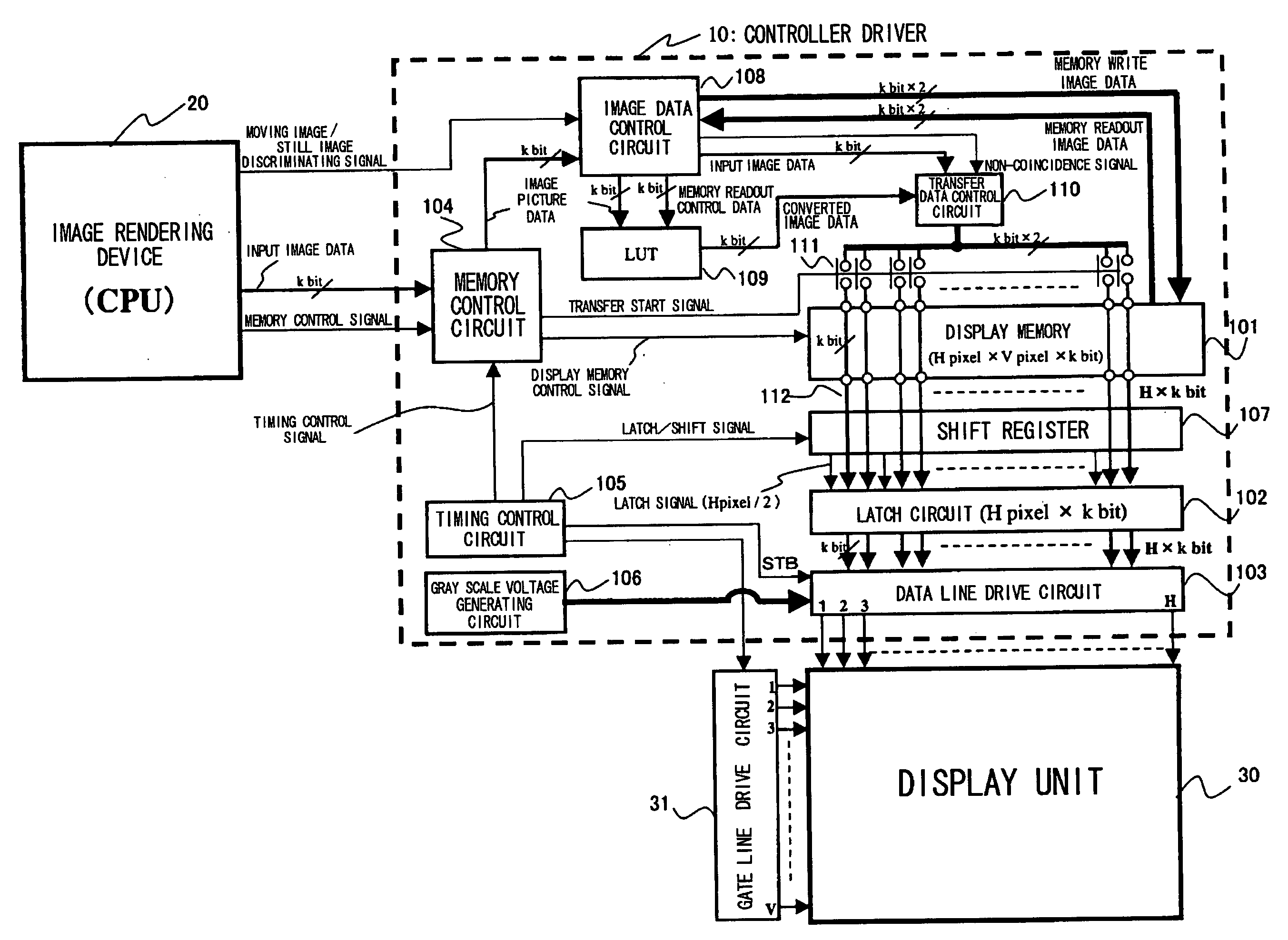
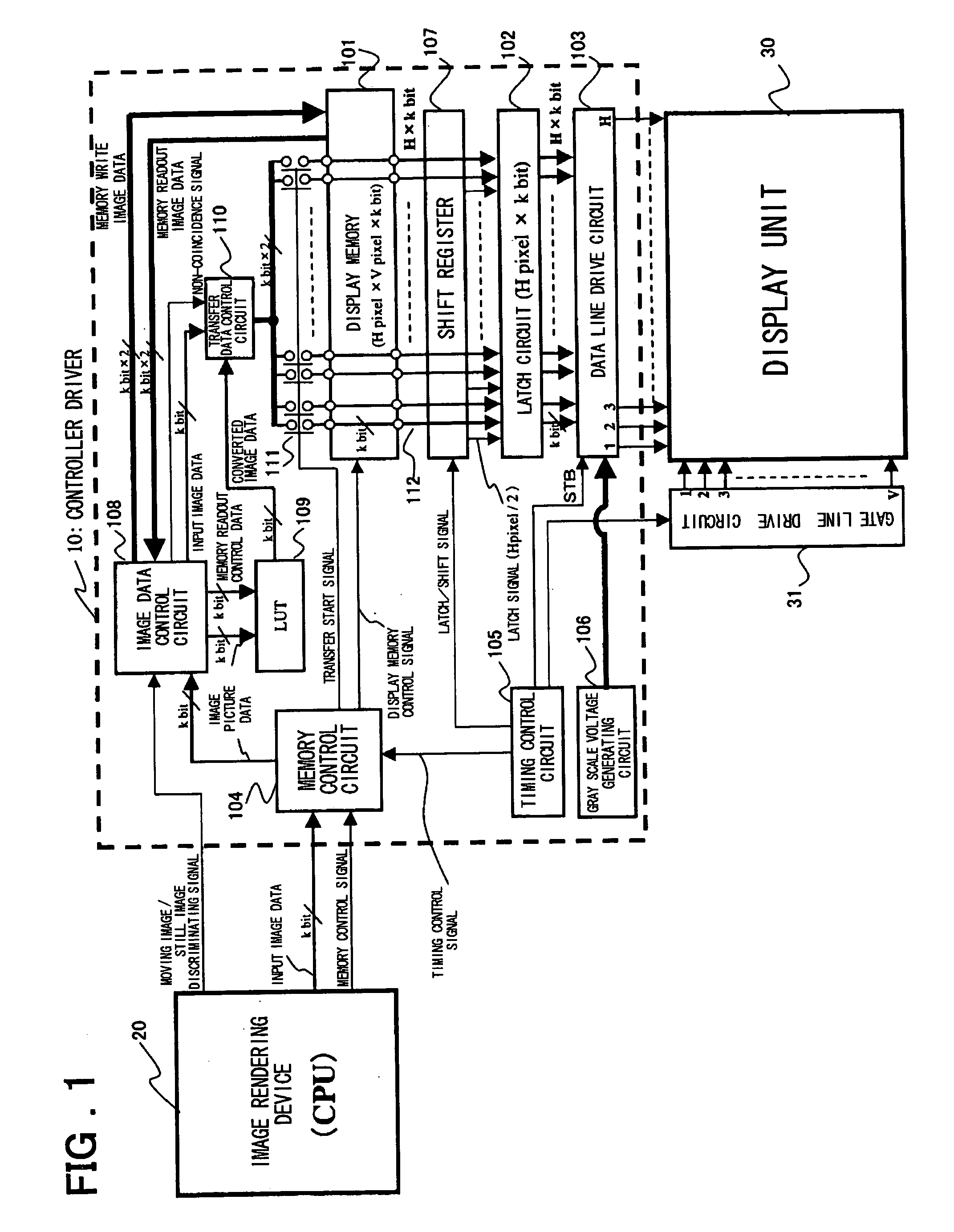
[0058]FIG. 1 shows the configuration of a first embodiment of the present invention. In FIG. 1, the controller driver 10 is arranged between an image rendering device 20 and a display unit 30 and includes a display memory 101, a set of latch circuits 102, a set of data line drive circuits 103, a memory control circuit 104, a timing control circuit 105, a grayscale voltage generating circuit 106, a shift register circuit 107, a image data control circuit 108, a lookup table 109, a transfer data control circuit 110, switches 111 and data transfer lines 112. The image rendering device 20 is composed e.g. by a CPU, whilst the display unit 30 is an LCD (liquid crystal display) or an EL (electro luminescence) display.

[0059] In the controller driver 10, the display memory 101 stores image data corresponding to one frame (H×V pixels)

[0060] The memory control circuit 104 receives input image data from the image rendering device 20, such as CPU and a memory control signal from the image ren...


PUM


Abstract

A driving apparatus for over-drive driving includes a display memory, a memory control circuit performing control for receiving input image data supplied from an image rendering device, reading out image data one frame before of the input image data from the display memory and for writing the input image data in the display memory as write image data for the display memory, and a image data control circuit for verifying whether or not the input image data from the memory control circuit coincides with the readout image data one frame before read out from the display memory. The apparatus also includes an LUT for outputting converted image data, a transfer data control circuit for selectively outputting the input image data or the converted image data, and latch circuits for latching image data of one horizontal line equivalent of pixels. A shift register circuit generates latch signal for image data.

Description

FIELD OF THE INVENTION [0001] The present invention relates to a display apparatus and, more particularly, to an apparatus, termed a controller driver, arranged between an upper layer apparatus and a display unit for exercising driving control of a data line of the display unit, and a display apparatus. BACKGROUND OF THE INVENTION [0002]FIG. 15 is a diagram showing an example of a typical configuration of a conventional controller driver 100 (for example, see Non-Patent Document 1 below). Referring to FIG. 15, the controller driver 100 (display control driving apparatus) is arranged between an image rendering device 20, such as CPU (central processing unit), as an upper layer device, and a display unit 30, for receiving image data for display from the image rendering device 20 to control the display thereof on the display unit 30, and includes a display memory 121 for storing image data for at least one frame (termed a frame memory), a latch circuit 122, a data line drive circuit 12...

Claims


Application Information

Patent Timeline
Patent Type & Authority Applications(United States)
IPC IPC(8): G09G3/36G09G3/20G09G5/00G09G5/06
CPCG09G3/3648G09G3/3688G09G2340/16G09G2320/0252G09G2320/103G09G2310/027
Inventor TESHIROGI, YOSHIYUKINOSE, TAKASHI
Owner RENESAS ELECTRONICS CORP
Why Eureka
Try Eureka