System and method for automatic chromatic dispersion compensation

a chromatic dispersion compensation and automatic technology, applied in the field of telecommunication techniques, can solve the problems of deviation from the optimal cumulative dispersion, significant degrade the detectability of the signal, and penalties for the receiver performance, so as to improve the chromatic dispersion tolerance, minimize distortion, and optimize the performance of the transmission system

Active Publication Date: 2005-11-17
FUTUREWEI TECH INC
View PDF15 Cites 10 Cited by
  • Summary
  • Abstract
  • Description
  • Claims
  • Application Information

AI Technical Summary

Benefits of technology

[0023] Many benefits are achieved by way of the present invention over conventional techniques. Certain embodiments of the present invention provide a method and system for increasing the chromatic dispersion tolerance in extended long haul optical fiber transmission systems, or in other optical fiber transmission systems where the dispersion tolerance is significantly narrowed due to the fiber nonlinearities. Some embodiments of the present invention provide a method and system for generating optical signals that self-adapt to the residual chromatic dispersion in dispersion compensated optical fiber transmission links so that the signals experience minimal distortions at the receivers. Certain embodiments of the present invention adjust the magnitude of the chirp on a CRZ signal in response to the variations in cumulative dispersion in dispersion compensated fiber routes. The adjustment is realized by changing the driving current, the driving voltage, or the driving RF power to a directly modulated laser in a transmitter. Some embodiments of the present invention use a performance-monitoring device on the receiver side. The performance monitoring device generates an output signal that can be used as feedback to control the driving current, the driving voltage, or the driving RF power for a directly modulated laser in a transmitter and therefore optimize the performance of a transmission system. Certain embodiments of the present invention provide a capability of shifting the center of the dispersion tolerance window and hence increasing the system tolerance to variations in cumulative dispersion. Some embodiments of the present invention can lower costs and reduce sizes of adaptive dispersion compensation systems. Certain embodiments of the present invention can adjust the center of the dispersion tolerance window and hence a large dispersion compensation range.

Problems solved by technology

For high-speed transmissions at over one gigabit per second, the bit periods are only a few hundred picoseconds, or even a few tens picoseconds; thus such broadening can significantly degrade the detectability of the signal.
Deviations from the optimal value of cumulative dispersion may cause penalties to the receiver performance.
Many factors may cause deviations from the optimal cumulative dispersion.
For example, unforeseen fiber cuts and repairs may change the value of the cumulative dispersion.
Additionally, the fiber dispersion is affected by temperature and aging.
In dense wavelength division multiplexing (DWDM) transmissions, the chromatic dispersion and its compensation is complicated.
Usually, adjustable optical dispersion compensators with large adjustment ranges are bulky and costly.
Since the dispersion occurs in the optical domain but the compensation is performed in the electronic domain, the compensation is usually very limited.

Method used


Image

  • System and method for automatic chromatic dispersion compensation
  • System and method for automatic chromatic dispersion compensation
  • System and method for automatic chromatic dispersion compensation

Examples


Embodiment Construction

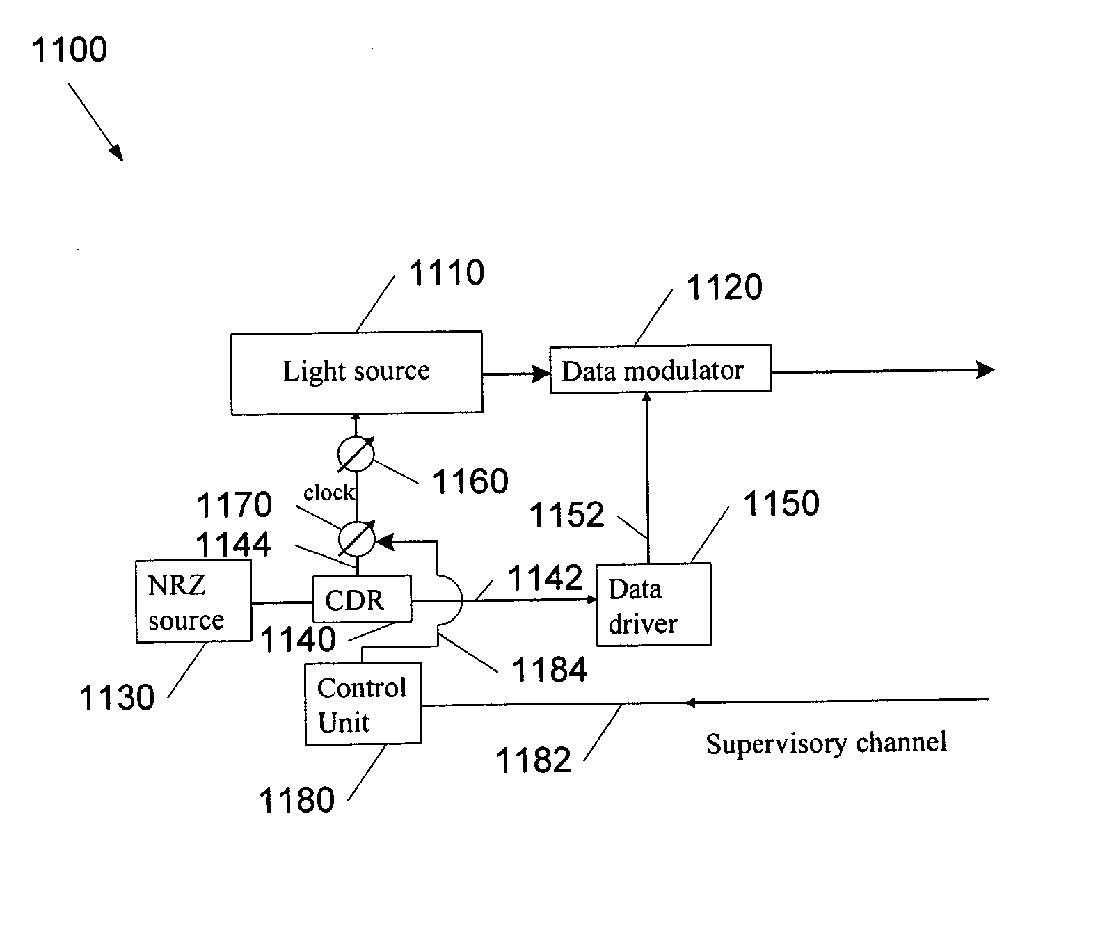
[0038] The present invention relates in general to telecommunication techniques. More particularly, the invention provides a method and system for automatic chromatic dispersion compensation. Merely by way of example, the invention is described as it applies to optical networks, but it should be recognized that the invention has a broader range of applicability.

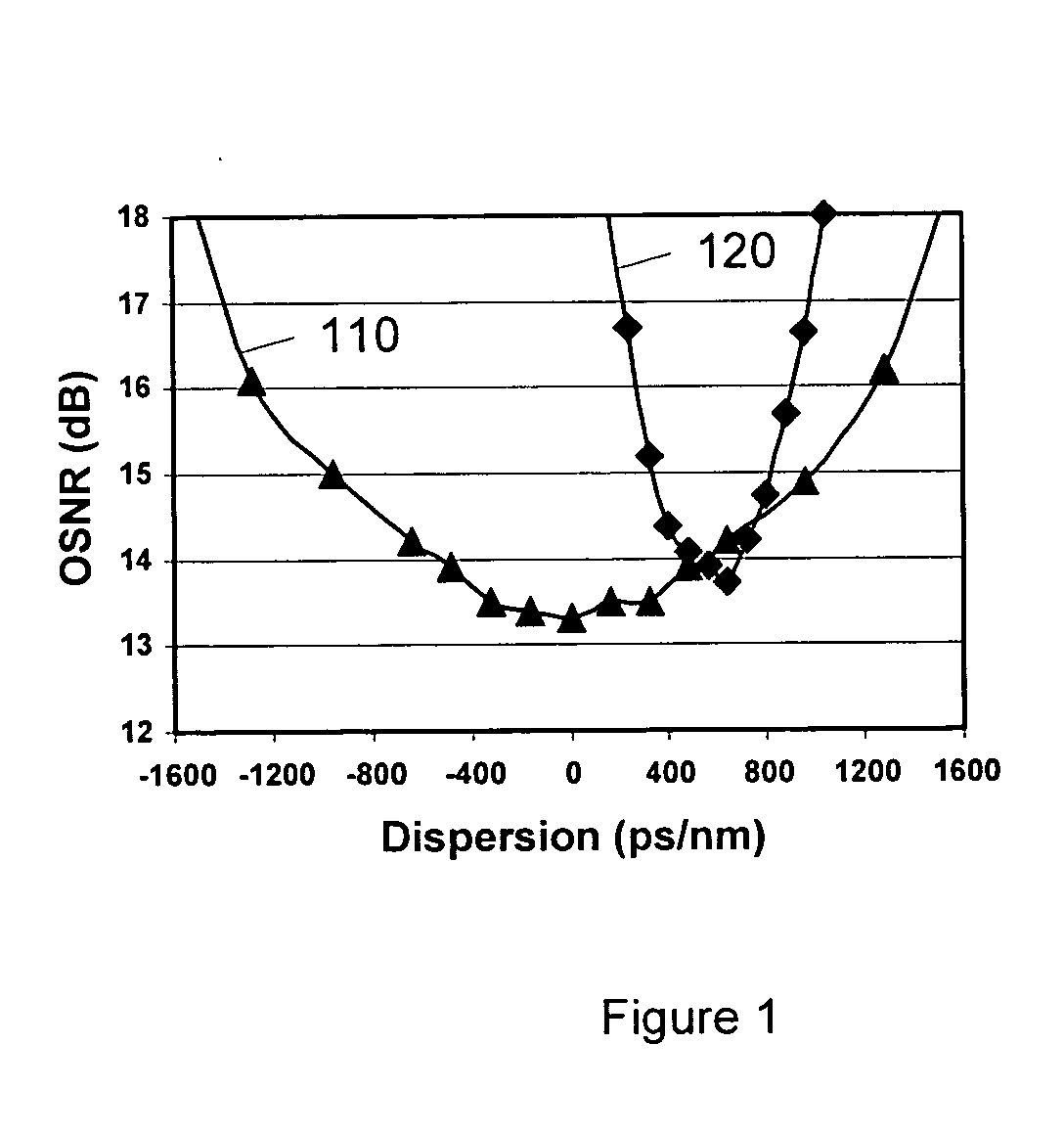
[0039] The dispersion limit for a chirp-free 10-Gbps NRZ signal is usually about 1200 ps / nm without dispersion compensation fiber (DCF). With DCF, the total cumulative dispersion can be negative as well as positive. The dispersion tolerance range thus expands to ±1200 ps / nm, and the total dispersion tolerance becomes 2400 ps / nm.

[0040]FIG. 1 is a simplified conventional dispersion tolerance for an NRZ signal. This diagram is merely an example, which should not unduly limit the scope of the claims. One of ordinary skill in the art would recognize many variations, alternatives, and modifications. The NRZ signal may be external...


PUM


Abstract

An apparatus and method for transmitting a signal for optical network applications with automatic chromatic dispersion compensation. The apparatus includes a first optical transmitter. The first optical transmitter includes a first light source configured to generate a first laser signal in response to a first laser drive signal, a first data modulator configured to receive the first laser signal and a first data drive signal and output a first chirped return-to-zero signal, and a first signal source configured to generate a first non-return-to-zero signal. Additionally, the apparatus includes a first clock and data recovery system, a first data driver, a first adjustment system, and a first control system.

Description

CROSS-REFERENCES TO RELATED APPLICATIONS [0001] This application is related to U.S. patent application Ser. No. 09 / 802,222 filed Mar. 8, 2001 and U.S. patent application Ser. No. 09 / 642,033 filed Aug. 18, 2000, both of which are incorporated by reference herein.STATEMENT AS TO RIGHTS TO INVENTIONS MADE UNDER FEDERALLY SPONSORED RESEARCH OR DEVELOPMENT [0002] NOT APPLICABLE REFERENCE TO A “SEQUENCE LISTING,” A TABLE, OR A COMPUTER PROGRAM LISTING APPENDIX SUBMITTED ON A COMPACT DISK [0003] NOT APPLICABLE BACKGROUND OF THE INVENTION [0004] The present invention relates in general to telecommunication techniques. More particularly, the invention provides a method and system for automatic chromatic dispersion compensation. Merely by way of example, the invention is described as it applies to optical networks, but it should be recognized that the invention has a broader range of applicability. [0005] Telecommunication techniques have progressed through the years. As merely an example, op...

Claims


Application Information

Patent Timeline
Patent Type & Authority Applications(United States)
IPC IPC(8): H04B10/00H04B10/08H04B10/155H04B10/18
CPCH04B10/0775H04B10/25137H04B2210/077H04B10/505H04B10/50577H04B10/504
Inventor BAI, YU SHENGZHANG, RONG
Owner FUTUREWEI TECH INC
Why Eureka
Try Eureka