Fastened vane assembly

a technology of fastening and vanes, which is applied in the direction of machines/engines, stators, liquid fuel engines, etc., can solve the problems of severe cracking of airfoils, and achieve the effect of minimizing leakag

Active Publication Date: 2005-11-17
H2 IP UK LTD
View PDF10 Cites 24 Cited by
  • Summary
  • Abstract
  • Description
  • Claims
  • Application Information

AI Technical Summary

Benefits of technology

[0006] It is an object of the present invention to provide a vane assembly having a plurality of airfoils that can respond individually to thermal gradients while minimizing leakage between the airfoils.
[0007] It is another object of the present invention to provide a means to connect a plurality of individual vanes together such that no modifications are required to the engine casing.

Problems solved by technology

As a result of this multi-vane configuration, the airfoils cannot respond as individual components thus creating high thermal stresses in vane assembly 10 resulting in severe cracking of airfoils 111 and 12 in a relatively short period of time.

Method used


Image

  • Fastened vane assembly
  • Fastened vane assembly
  • Fastened vane assembly

Examples


Embodiment Construction

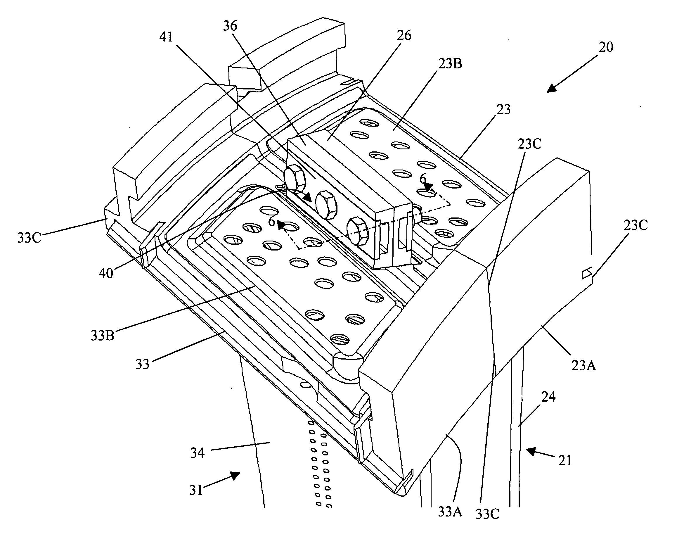
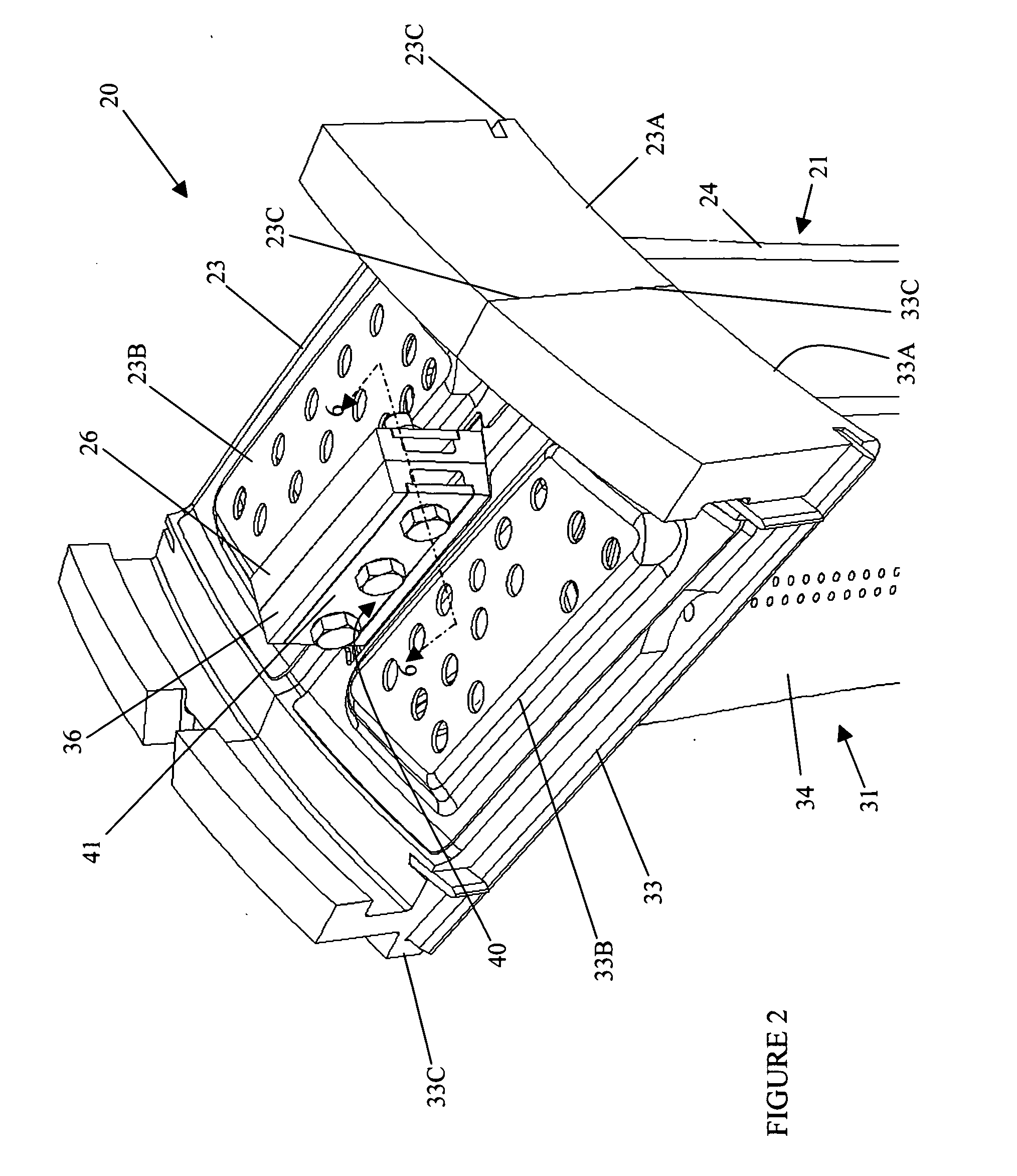
[0016] A vane assembly 20 for a gas turbine in accordance with the preferred embodiment of the present invention is shown in detail in FIGS. 2-7. Vane assembly 20 comprises first vane 21, which in turn, comprises first inner platform 22, first outer platform 23, first airfoil 24, first inner flange 25, and first outer flange 26. First inner platform 22 further comprises first inner hot wall 22A, first inner cold wall 22B, and first inner edge 22C, while first outer platform 23 further comprises first outer hot wall 23A, first outer cold wall 23B, and first outer edge 23C. First airfoil 24 extends generally radially between first inner hot wall 22A and first outer hot wall 23A. First inner flange 25 is fixed to first inner cold wall 22B and has at least one first inner hole 25A having a first inner diameter. Meanwhile, first outer flange 26 is fixed to first outer cold wall 23B and has at least one first outer hole 26A having a first outer diameter. Referring to FIGS. 3 and 5, in the...


PUM


Abstract

A vane assembly for a gas turbine is described wherein the vane assembly comprises a first vane and a second vane connected together by a plurality of flanges, at least one fastener, and at least one spring plate. The fastener and hole diameters in the respective flanges are sized such that the first vane and second vane are essentially pinned together along their inner flanges and allowed to adjust due to thermal growth along their outer flanges, while maintaining a constant seal along both inner and outer platform edges. The thermal growth along the outer flanges is made possible by oversized flange holes relative to the diameter of the fastener.

Description

TECHNICAL FIELD [0001] The present invention relates generally to gas turbine engines and more specifically to a turbine vane assembly comprising a plurality of individual vanes. BACKGROUND OF THE INVENTION [0002] A gas turbine engine typically comprises a compressor, combustion system, and turbine, for the purpose of compressing air, mixing it with a fuel and igniting this mixture, and directing the resulting hot combustion gases through a turbine for creating propulsive thrust or rotational energy used for electrical generation. Turbine sections comprise a plurality of stages, where each stage includes a row of stationary airfoils followed by a row of rotating airfoils, where the row of stationary airfoils direct the flow of hot combustion gases onto the row of rotating airfoils at a preferred angle. The rotating airfoils of the turbine are driven by the pressure load from the hot combustion gases passing along the airfoil surface. While the rotating airfoils, or blades, are each ...

Claims


Application Information

Patent Timeline
Patent Type & Authority Applications(United States)
IPC IPC(8): F01D1/02F01D9/04
CPCF01D9/042F05D2230/642F05D2260/30F05D2240/80
Inventor BASH, GARYSTROHL, J. PAGE
Owner H2 IP UK LTD
Why Eureka
Try Eureka