

Massage device
a technology of massage device and massage head, which is applied in the field of massage devices, can solve the problem of providing a single massage
- Summary
- Abstract
- Description
- Claims
- Application Information
AI Technical Summary
Benefits of technology
Problems solved by technology
Method used
Image

Examples
first embodiment
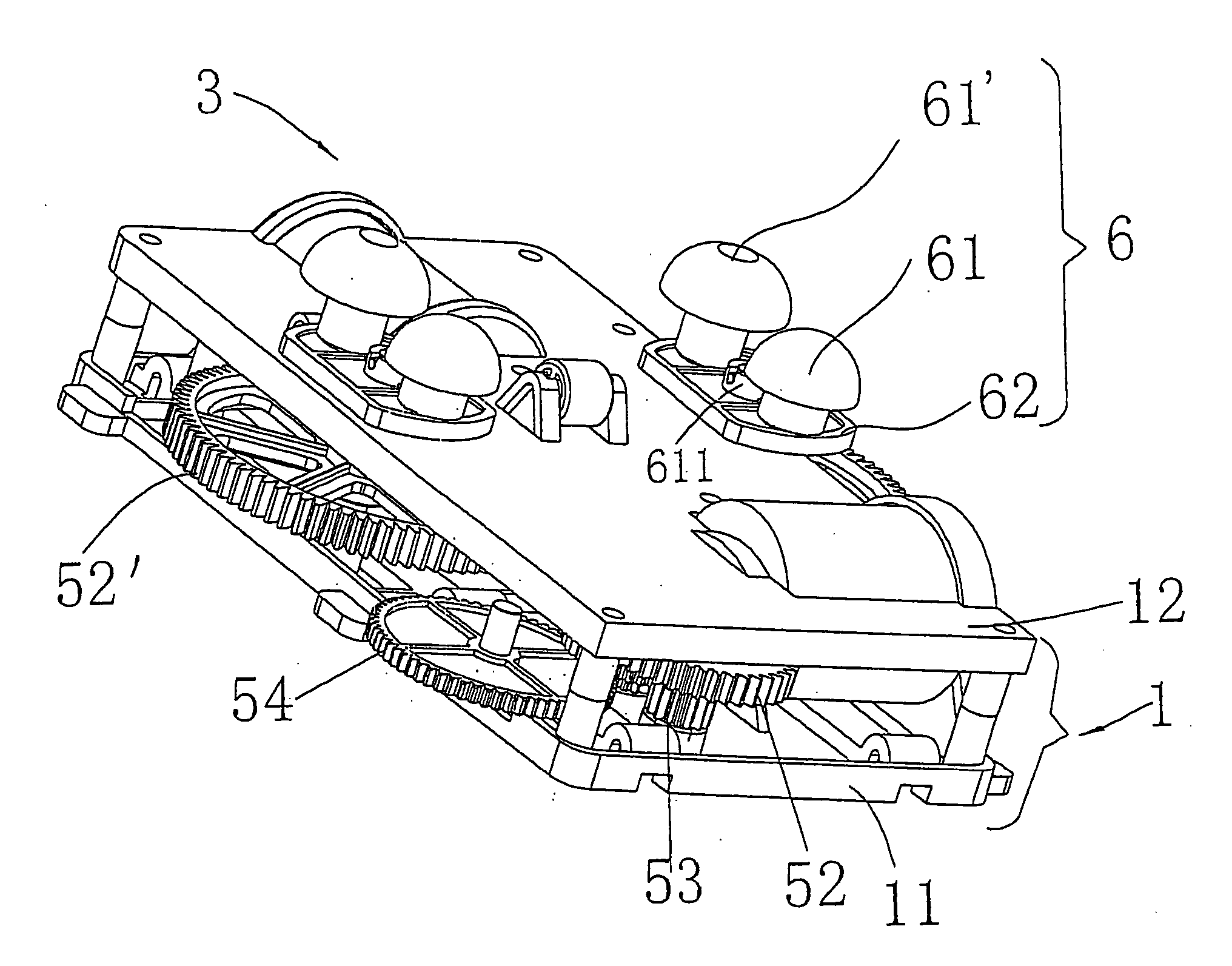
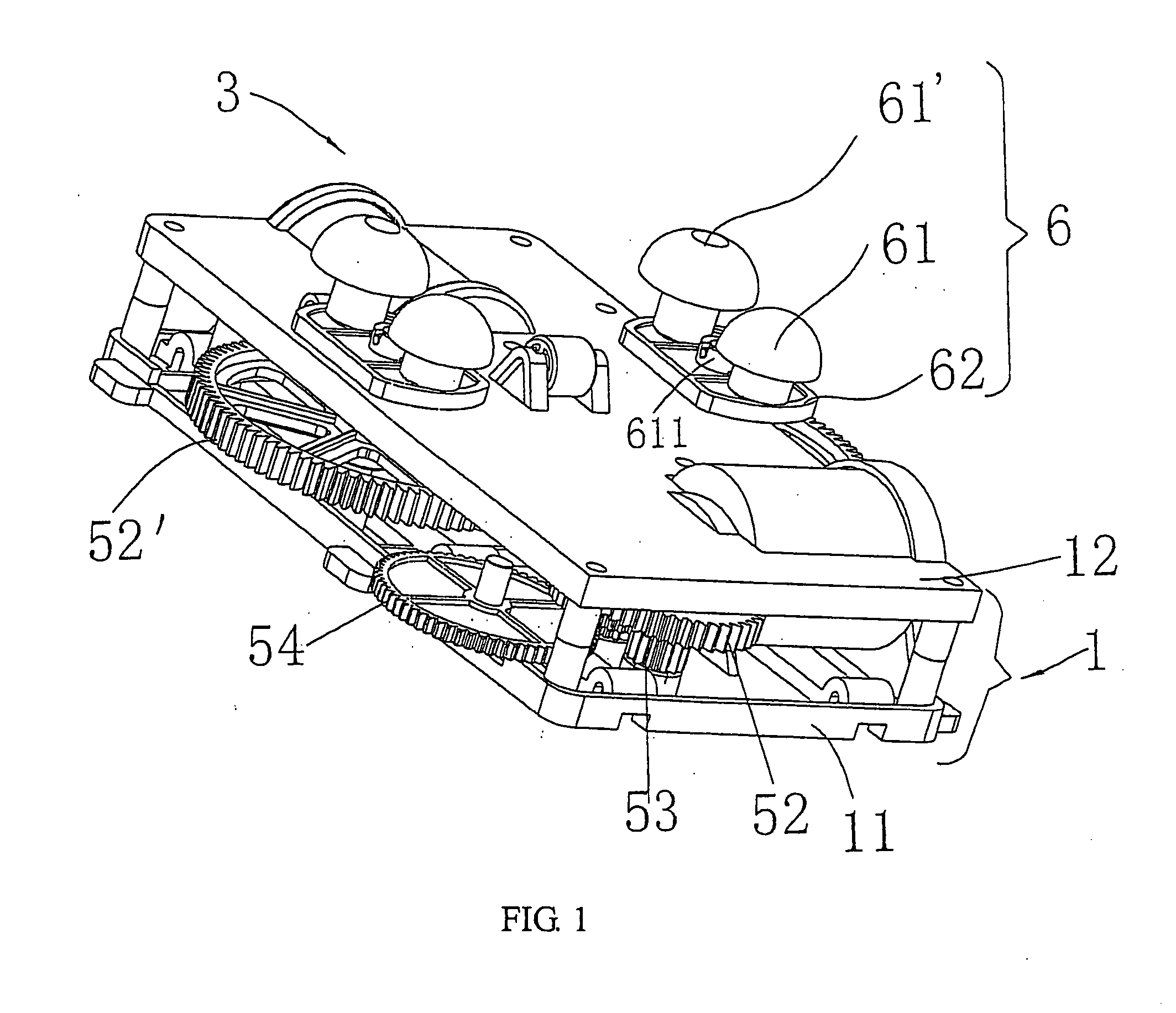
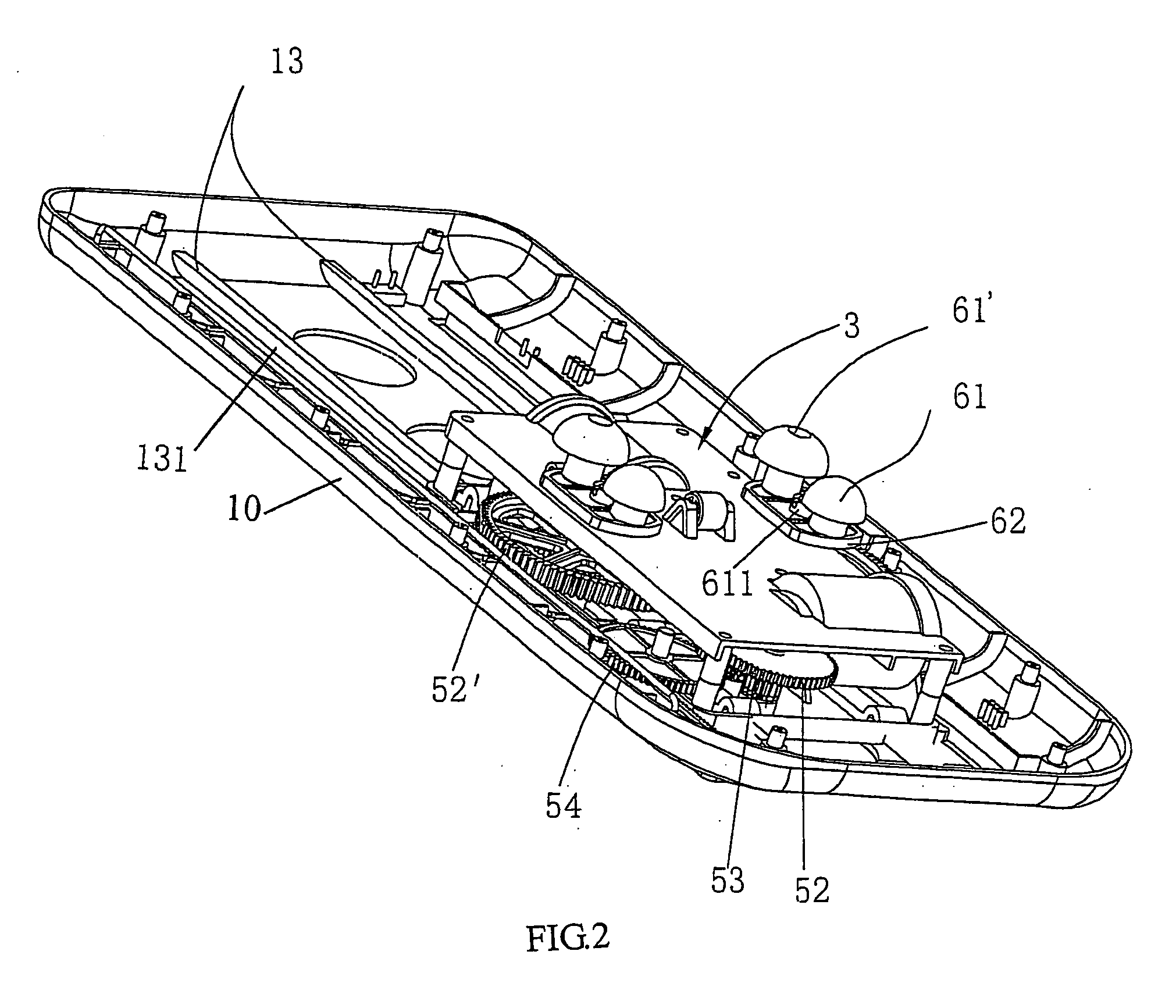
[0026] Referring to FIGS. 1-3, according to the invention, a massage device comprises a base cover 10, a guide device 13 and a moving base 3. The guide device 13 is constituted by a plurality of guide rails 131 positioned in the middle of the base cover 10. The moving base 3 comprises a bottom 11 and a shield 12. The shield 12 covers on the bottom 11 so as to form a chassis 1. Two motors 4 and 4′ are assembled between the bottom 11 and the shield 12; a transmission system 5 and a massage system 6 positioned on the shield 12. The moving base 3 is suspended above the guide device 13 and can move in an area defined by the guide device 13. In the invention, the motors 4 and 4′ are set in a certain angle, which are provided with worm 51 and 51′ on its output end. Two worm wheels 52 and 52′ are joggled with and drived in-phase by the worm 51 and 51′ of the motor 4 and 4′ respectively. The two worm wheels 52 and 52′ are pivoted in the moving base 3 comparatively. Each of worm wheel shafts ...
second embodiment
[0028] As shown in FIGS. 4-6, according to the invention, a massage device comprises a base cover 10, a guide device 13 and a moving base 3. The moving base 3 comprises a bottom 11 and a shield 12 covered thereon so as to form a chassis. The guide device 13 is constituted by a plurality of guide rails 131 positioned in the middle of the base cover 10. The moving base 3 comprises a single motor 4 which is assembled between the bottom 11 and the shield 12; a transmission system 5 and a massage system 6 positioned on the shield 12. The moving base 3 is suspended above the guide device 13 and can move in an area defined by the guide device 13. In the invention, the motor 4 is provided with worm 51 on its output end. Two worm wheels 52 and 52′ are joggled with and drived in-phase by the worm 51 of the motor 4. The two worm wheels 52 and 52′ are pivoted in the moving base 3 comparatively. Each of worm wheel shafts 52′a of the worm wheels 52, 52′ has its top end mounted in a middle shaft b...
third embodiment
[0030] As shown in FIGS. 8-9, according to the invention, a massage device comprises a base cover 10, a guide device 13 and a moving base 3. The moving base 3 comprises a bottom 11 and a shield 12 covered thereon so as to form a chassis. The guide device 13 is constituted by a plurality of guide rails 131 positioned in the middle of the base cover 10. The moving base 3 comprises a single motor 4 which is assembled between the bottom 11 and the shield 12; a transmission system 5 and a massage system 6 positioned on the shield 12. The moving base 3 is suspended above the guide device 13 and can move in an area defined by the guide device 13. In the embodiment, the motor 4 is mounted in a groove 141 at front end of the bottom 11. The moving base 3 further comprises a guide rail 131 with a rail groove 1311, a worm 51 on the output end of the motor 4, a worm wheels 52, a rack 17 provided on side of guide rail 131. The worm wheel 52 is joggled with and drived by the worm 51. The moving ba...
PUM
 Abstract
Description
Claims
Application Information