Horizontally assembled steam generator

a horizontal assembly and steam generator technology, applied in steam generation heating methods, steam generation using hot heat carriers, water circulation, etc., can solve the problems of reduced steam generation efficiency, unsatisfactory efficiency losses, and comparative reduction in the effectiveness of the heating area concerned, and achieve low overall pressure loss and simplify the effect of distribution

Inactive Publication Date: 2005-11-24
SIEMENS AG
View PDF4 Cites 6 Cited by
  • Summary
  • Abstract
  • Description
  • Claims
  • Application Information

AI Technical Summary

Benefits of technology

[0010] The object of the invention is therefore to provide a steam generator of the aforementioned type in which a particularly high degree of flow stability during operation of the evaporator heating area connected as a once-through heating area or evaporator / once-through heating area can be achieved at a comparatively low construction and design cost.
[0012] The invention is based on the idea that the construction and design cost in setting up the steam generator can be kept low by reducing to a particular extent the number of component types used. Such a reduction of components can be achieved in the case of the steam generator of the aforementioned type by economizing on the distributor system connected downstream of the once-through heating area, by making consistent use of the property of the once-through heating area which is in any case provided, namely the self-stabilizing circulation characteristic. It is precisely because of this characteristic that the mixing of the flow medium flowing out of different steam-generator tubes connected in parallel to one another and its transfer to the heating-area system connected downstream, without any significant impairment of the homogenization achieved by the mixing can be shifted from a downstream distributor system to the discharge collector connected in any case downstream of the steam-generator tubes, without this leading to any significant flow instabilities or other problems. Accordingly, the comparatively costly distributor system can be dispensed with. A design of the discharge collector that is appropriate for this purpose, namely for the appropriate mixing and forwarding of the flow medium flowing out of the steam-generator tubes, can be achieved whereby the steam-generator tubes of the evaporator / once-through heating area which are arranged behind one another, viewed in the heating-gas direction, and are thus, in terms of their heating profile, exposed to locally differing levels of heating discharge at the outlet end into a common collecting chamber. Such a common collecting chamber for the steam-generator tubes arranged behind one another, viewed in the heating-gas direction, is enabled by the discharge collector being oriented with its longitudinal axis essentially parallel to the heating-gas direction.
[0013] A particularly simple method of construction of the discharge collector can intrinsically be achieved by fashioning said discharge collector essentially as a cylindrical body.
[0020] Due to the essentially U-shaped design of the steam-generator tubes which form the further once-through heating area, their intake area is located in the upper region of or above the heating-gas duct. Here, consistent use of the discharge collectors, which are assigned to the evaporator / once-through heating area, are disposed above the heating-gas duct and are oriented with their longitudinal direction in each case essentially parallel to the direction of flow of the heating gas, enables an interconnection of the evaporator / once-through heating area and the further evaporator / once-through heating area at especially low cost in that the discharge collector or each discharge collector of the evaporator / once-through heating area is integrated with a respectively assigned entry collector of the evaporator / once-through heating area connected downstream on the flow-medium side in an advantageous design into a structural unit. Such an arrangement enables a direct overflow of the flow medium being discharged from the first evaporator / once-through heating area into steam-generator tubes of the further evaporator / once-through heating area which are connected downstream on the flow-medium side. Costly distributor or connection lines between the discharge collector of the evaporator / once-through heating area and the entry collector of the further evaporator / once-through heating area, as well as assigned mixing and distributor elements can be dispensed with, and the line layout is in general relatively simple.
[0021] In a further advantageous embodiment, the steam-generator tubes of the further evaporator / once-through heating area are connected at the inlet end to the entry collectors assigned to each of them in a common plane oriented perpendicularly to the longitudinal axis of the discharge collectors and thus perpendicularly to the heating-gas direction. Such an arrangement ensures that the partly evaporated flow medium to be fed to the further evaporator / once-through heating area, starting from the part of the integrated unit used as a discharge collector for the first evaporator / once-through heating area, first strikes the base of the part of the structural unit used for the further evaporator / once-through heating area, is swirled once again there and then flows out with virtually identical two-phase proportions into the steam-generator tubes of the further evaporator / once-through heating area which are connected to the respective entry collector. Forwarding of the flow medium into the steam-generator tubes of the further evaporator / once-through heating area is thus promoted without any significant impairment of the homogenization achieved by the mixing in the discharge collector, whereby a particularly homogeneous flow medium is fed to the further once-through heating area simply because of the symmetrical arrangement of the discharge points from the respective entry collector relative to the longitudinal axis of the collector unit.
[0023] The advantages achieved by means of the invention are in particular that as a result of the orientation of the discharge collector parallel to the heating-gas direction the property of the evaporator / once-through heating area which is in any case provided, namely a self-stabilizing circulation characteristic, can be utilized consistently for simplifying the distribution. It is precisely because of the self-stabilizing circulation characteristic that steam-generator tubes arranged behind one another, viewed in the heating-gas direction, can now also discharge at the outlet end with approximately equal steam states into a common discharge collector. In said discharge collector, the flow medium flowing out of the steam-generator tubes is mixed and prepared for forwarding to a subsequent heating-area system without impairing the homogenization achieved in the mixing process. In particular, the integration of outlet and entry collectors makes it possible for a separate distributor system, which is connected downstream of the evaporator / once-through heating area and is comparatively costly, to be dispensed with. Furthermore, the steam generator fashioned in this manner exhibits a comparatively low overall loss of pressure on the flow-medium side.

Problems solved by technology

Particularly where steam-generator tubes of a once-through steam generator are connected on the outlet side to a common collector, different heating of individual steam-generator tubes may lead to the merging of steam flows having steam parameters differing greatly from one another and thus to undesirable efficiency losses, in particular to a comparative reduction in the effectiveness of the heating area concerned and consequently to a reduction in steam generation.
Different heating of adjacent steam-generator tubes, particularly in the region where they lead into collectors, may also result in damage to the steam-generator tubes or the collector.
The inherently desirable use of a once-through steam generator with a horizontal type of construction as a waste-heat stem generator for a gas turbine can thus bring with it considerable problems with regard to an adequately stabilized flow.

Method used


Image

  • Horizontally assembled steam generator
  • Horizontally assembled steam generator
  • Horizontally assembled steam generator

Examples


Embodiment Construction

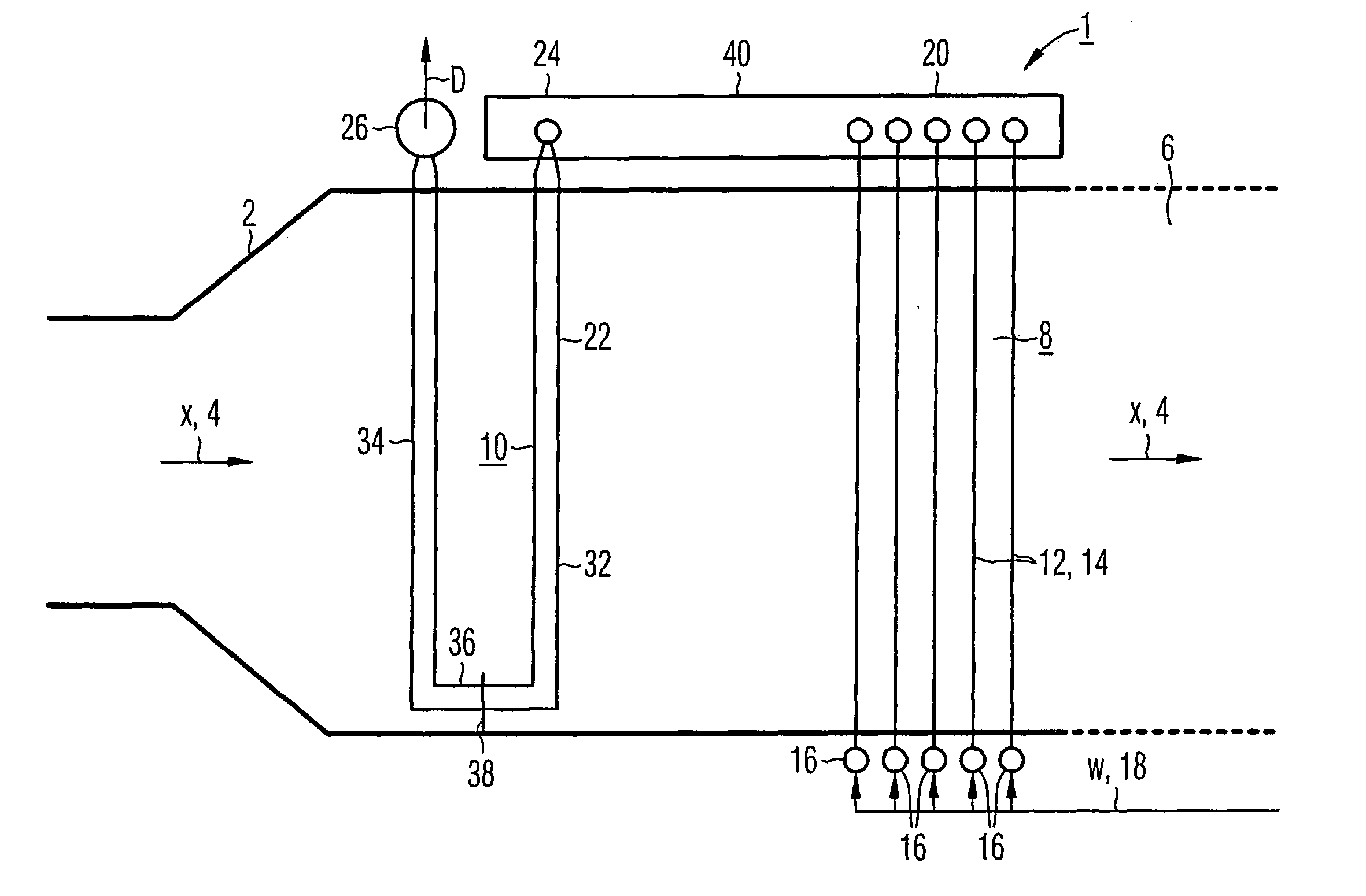
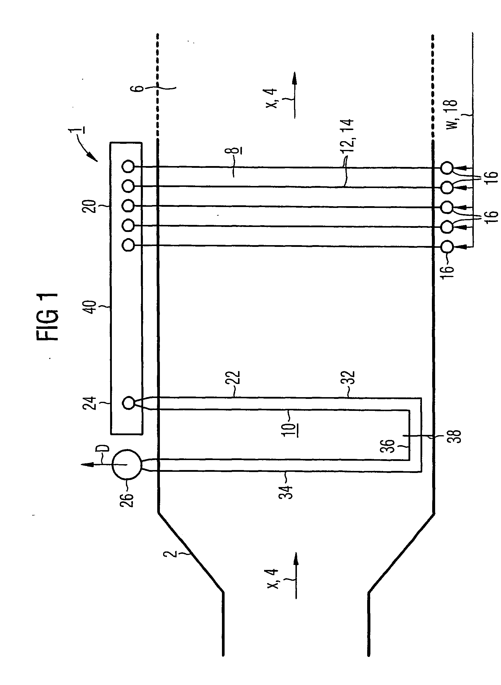
[0031] The steam generator 1 shown with its evaporator section in FIG. 1 is connected downstream in the manner of a waste-heat steam generator at the exhaust-gas end of a gas turbine, not shown in detail. The steam generator 1 has a containing wall 2 which forms a heating-gas duct 6 for the exhaust gas from the gas turbine, through which heating-gas duct said exhaust gas can flow in a approximately horizontal heating-gas-direction x indicated by the arrows 4. In the heating-gas duct 6 there are disposed a number (in the embodiment two) of evaporator heating areas 8, 10 which are configured in accordance with the once-through principle and which are connected behind one another for through flow by a flow medium W, D.

[0032] The multi-stage evaporator system formed from the evaporator / once-through heating areas 8, 10 can be loaded with a non-evaporated flow medium W which evaporates in a single pass through the evaporator / once-through heating areas 8, 10 and, after discharge from the ...


PUM


Abstract

Disclosed is a steam generator in which a continuous evaporating heating area is disposed within a heating gas duct that is penetrated in a nearly horizontal direction by a heating gas. Said continuous evaporating heating area comprises a number of steam-generating pipes that are connected in parallel and are penetrated by a flowing medium and is configured such that a steam-generating pipe which is heated more than another steam-generating pipe of the same continuous evaporating heating area has a higher throughput of the flowing medium than said other steam-generating pipe. The aim of the invention is to create a steam generator which provides a particularly high degree of stability of flow during operation of the continuous evaporating heating area while keeping the structural complexity and design comparatively simple. Said aim is achieved by means of a discharge collector which is mounted downstream of the steam-generating pipes of the continuous evaporating heating area on the side of the flowing medium, and the longitudinal axis of which is located essentially parallel to the direction of the heating gas.

Description

CROSS REFERENCE TO RELATED APPLICATION [0001] This application is the US National Stage of International Application No. PCT / EP2003 / 009571, filed Aug. 28, 2003 and claims the benefit thereof. The International Application claims the benefits of European Patent application No. 02020252.9 EP filed Sep. 10, 2002, both of the applications are incorporated by reference herein in their entirety.FIELD OF THE INVENTION [0002] The invention relates to a steam generator in which an evaporator / once-through heating area is disposed within a heating-gas duct through which a flow can be conducted in an approximately horizontal heating-gas direction, said evaporator / once-through heating area comprising a number of steam-generator tubes connected in parallel for a through-flow of a flow medium and being configured such that a steam-generator tube which is heated to a greater extent compared with a further steam-generator tube of the same evaporator / once-through heating area has a higher throughput ...

Claims


Application Information

Patent Timeline
Patent Type & Authority Applications(United States)
IPC IPC(8): F22B1/18F22B29/06F22B37/22
CPCF22B1/1815
Inventor FRANKE, JOACHIMKRAL, RUDOLFWITTCHOW, EBERHARD
Owner SIEMENS AG
Why Eureka
Try Eureka