Compression pulse starting of a free piston internal combustion engine

a technology of internal combustion engine and compression pulse, which is applied in the direction of engine starter, machine/engine, muscle operated starter, etc., can solve the problems of partial vacuum in the cylinder, leakage of air charge from the cylinder through the inlet and exhaust ports, and leakage, so as to increase the kinetic energy, and the effect of sufficient magnitude of kinetic energy

Inactive Publication Date: 2005-11-24
FORD GLOBAL TECH LLC
View PDF19 Cites 8 Cited by
  • Summary
  • Abstract
  • Description
  • Claims
  • Application Information

AI Technical Summary

Benefits of technology

[0008] To avoid relying on large hydraulic or pneumatic pressures in the starting actuator a cyclic starting strategy has been developed. The pistons are reciprocated during starting with a progressively increasing displacement (or compression ratio) in order to develop a sufficient magnitude of kinetic energy in the pistons to produce combustion of the fuel-air charge. Energy applied to the piston in each cylinder by a starting actuator and energy recovered from expansion of the compressed charge in the other cylinder before combustion occurs combine to increase the kinetic energy of the reciprocating pistons and to steadily increase pressure in the combustion chamber. During the process, part of the compression energy is transmitted to the compressed air and the energy is increased cycle-by-cycle.

Problems solved by technology

If the engine is stopped with a piston in the compression stroke, leakage of the air charge from the cylinder through the inlet and exhaust ports and across the piston rings will occur during the shutdown period due to the pressure in the cylinder.
This leakage can produce a partial vacuum in the cylinder when the piston begins to move in the expansion stroke.

Method used


Image

  • Compression pulse starting of a free piston internal combustion engine
  • Compression pulse starting of a free piston internal combustion engine
  • Compression pulse starting of a free piston internal combustion engine

Examples


Embodiment Construction

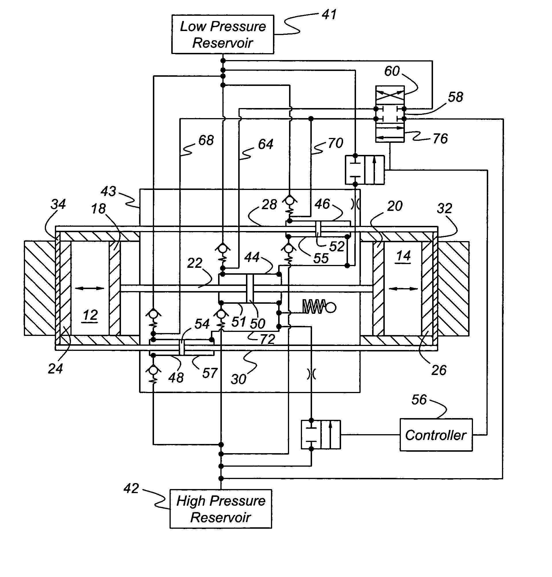
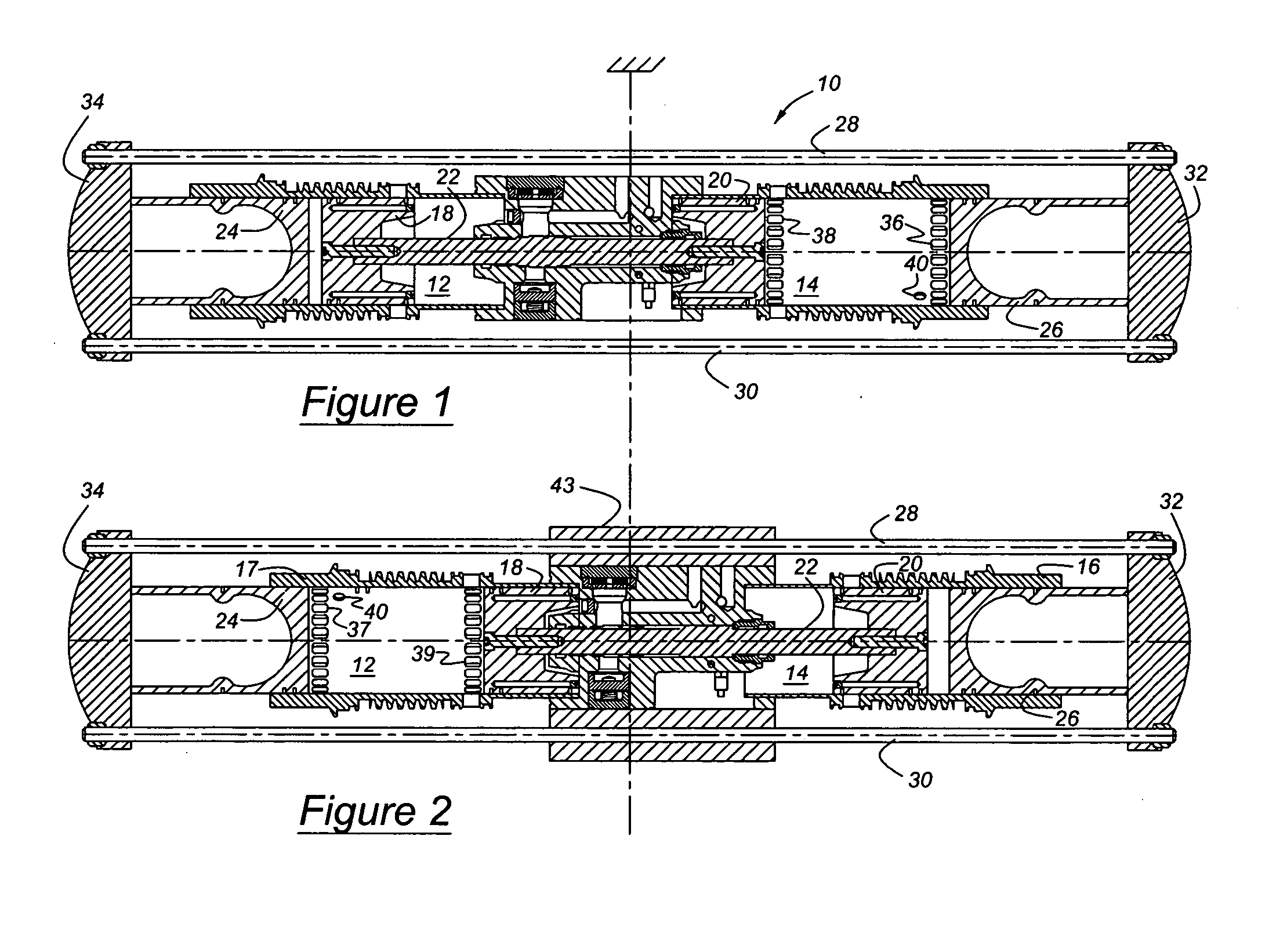
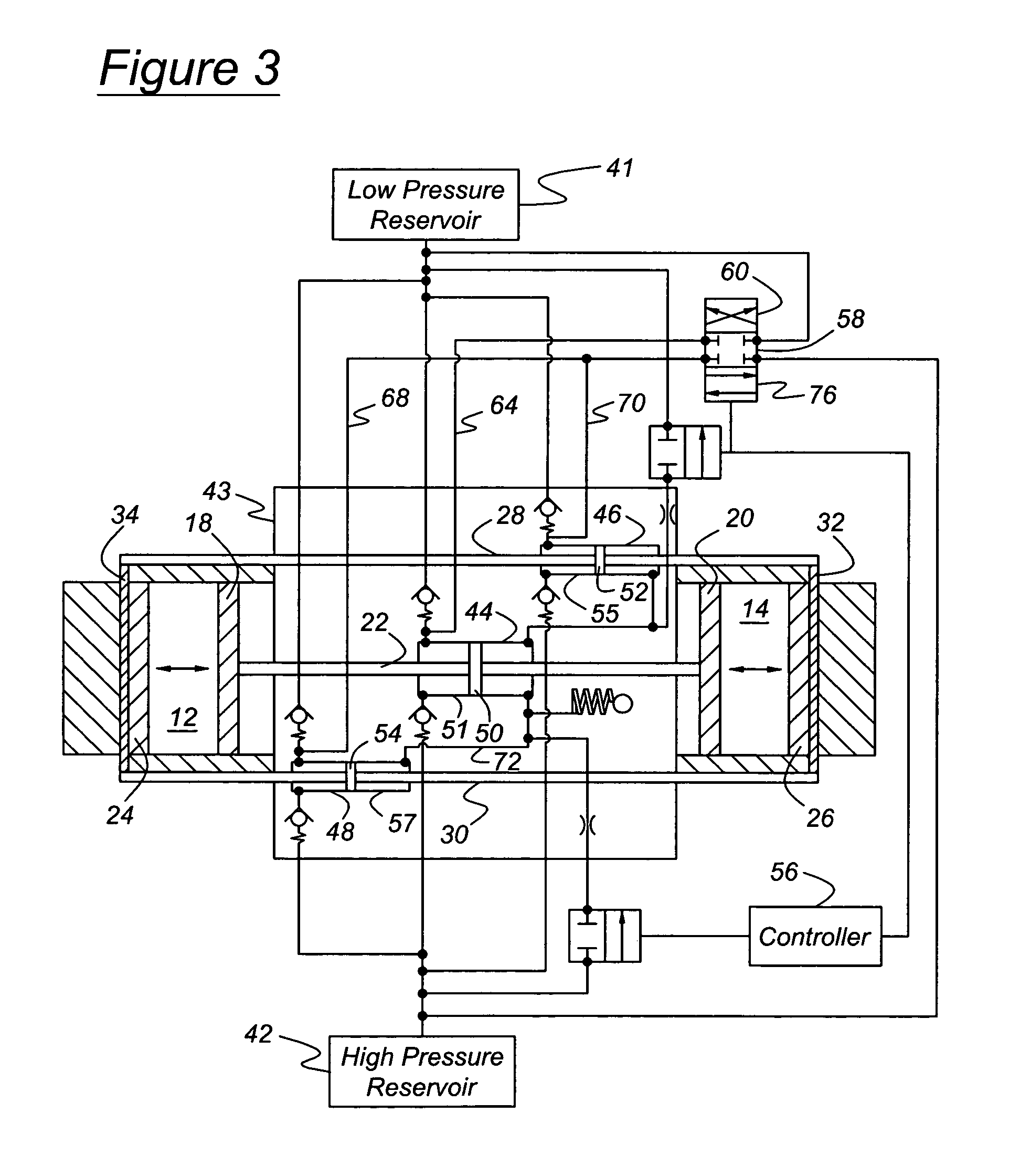
[0015] Referring first to FIGS. 1 and 2, a free piston engine 10 includes a first cylinder 12 and a second cylinder 14, axially aligned with the first cylinder, the cylinders being located in cylinder liners or engine blocks 16, 17. A first pair of pistons, inner pistons 18, 20, are mutually connected by a push rod 22. A first piston 18 of the first piston pair reciprocates within the first cylinder 12, and the second piston 20 of the first piston pair reciprocates within the second cylinder 14. A second pair of pistons, outer piston 22, 24, are connected mutually by pull rods 28, 30, secured mutually at the axial ends of pistons 24, 26 by bridges 32, 34. A first piston of the second or outer piston pair reciprocates within the first cylinder 12, and a second piston 26 of the outer piston pair reciprocates within the first cylinder 14. Each cylinder 12, 14 is formed with air inlet ports 36, 37 and exhaust ports 38, 39. In FIG. 1, the ports 37, 39 of cylinder 12 are closed by pistons...


PUM


Abstract

A method for starting an engine uses an actuator, such as a hydraulic or pneumatic pump-motor or an electric linear alternator-starter to move the pistons to a position where the inlet ports are opened. This ensures that air is present in the cylinder in a space where fuel will be admitted and combustion will occur. This strategy compresses, with a minimum actuator capacity, such air to a state that the pressure and temperature satisfy the ignition requirements. The air stores kinetic energy of the moving pistons that partially form the air spring force of the opposite cylinder and partially from the actuator. Accumulation, cycle by cycle, of this stored energy accelerates the piston motion, increases the piston displacement, and increases the compression ratio. The cylinder pressure and temperature increas cycle by cycle until the fuel ignition conditions are satisfied. The actuator force is a periodic force preferably having a frequency that is the same or nearly the same as the natural frequency of the system that includes the inertia of the pistons and other masses reciprocating with the pistons and the variable spring, represented by the compressible air spring in the combustion chamber. When piston displacement reaches a sufficient magnitude, fuel is admitted to the air charge, preferably by injection. The actuator continues to increase piston displacement and the compression pressure of the air-fuel mixture in the cylinder until combustion of that mixture in the first cylinder occurs. Fuel is then admitted to the second cylinder while continuing cyclic displacement of the pistons, and combustion of the fuel-air mixture in the second cylinder occurs.

Description

BACKGROUND OF THE INVENTION [0001] The invention relates to starting an internal combustion engine. In particular, the invention pertains to steadily increasing piston displacement, and thus the compression ratio, by applying and increasing a periodic force to a piston reciprocating against a compressible air charge while starting a free piston engine. [0002] A free piston internal combustion engine includes one or more reciprocating pistons located in a combustion cylinder. A crankshaft does not mutually connect the pistons. Instead, each piston moves in response to forces produced by combustion of an air-fuel mixture in a combustion cylinder. Pressure produced by combustion in one cylinder can be used to compress an air-fuel charge in another cylinder. Or an actuating system can be used to compress the air-fuel mixture following the expansion stroke. The actuating system may be used also to reciprocate the piston while starting the engine before combustion of an air-fuel mixture o...

Claims


Application Information

Patent Timeline
Patent Type & Authority Applications(United States)
IPC IPC(8): F02B71/00F02B71/02F02N7/06F02N99/00
CPCF02N7/06F02B71/02
Inventor PENG, LIXINLIU, JING PINGYANMIN, WANG
Owner FORD GLOBAL TECH LLC
Why Eureka
Try Eureka