Gravity valve for a downhole tool

a gravity valve and tool technology, applied in the direction of valve operating means/release devices, borehole/well accessories, sealing/packing, etc., can solve the problems of frac plugs and cement retainers being destructively removed, the inner diameter of mandrels being uneven, and the production of the lower and upper zones may continue concomitantly, so as to improve the removal of tools

Inactive Publication Date: 2005-11-24
BJ SERVICES CO
View PDF70 Cites 73 Cited by
  • Summary
  • Abstract
  • Description
  • Claims
  • Application Information

AI Technical Summary

Benefits of technology

[0015] A gravity valve for use in composite frac plugs, traditional cast iron frac plugs, or other downhole tools is disclosed. In some embodiment, the gravity valve has components compri

Problems solved by technology

For instance, when fracturing (“fracing”) a well, it is desirable to provide fluid communication from the formation or reservoir to surface, while not permitting fluid to flow downwardly though the tool.
Once the pumping of the frac fluid ceases, production from the lower and upper zone may continue concomitantly.
One prior art system for controlling the flow of fluid through a downhole tool is exemplified by the tool having packer on a hollow mandrel, the mandrel having an inner diameter which is not uniform.
In some instances, once the frac plugs or cement retainers have completed their function, the frac plugs and cement retainers are destructively

Method used


Image

  • Gravity valve for a downhole tool
  • Gravity valve for a downhole tool
  • Gravity valve for a downhole tool

Examples


Embodiment Construction

[0031] Illustrative embodiments of the invention are described below. In the interest of clarity, not all features of an actual implementation are described in this specification. It will of course be appreciated that in the development of any such actual embodiment, numerous implementation-specific decisions must be made to achieve the developers' specific goals, such as compliance with system-related and business-related constraints, that will vary from one implementation to another. Moreover, it will be appreciated that such a development effort might be complex and time-consuming, but would nevertheless be a routine undertaking for those of ordinary skill in the art having the benefit of this disclosure.

[0032] Structure of Embodiments of a Gravity Valve

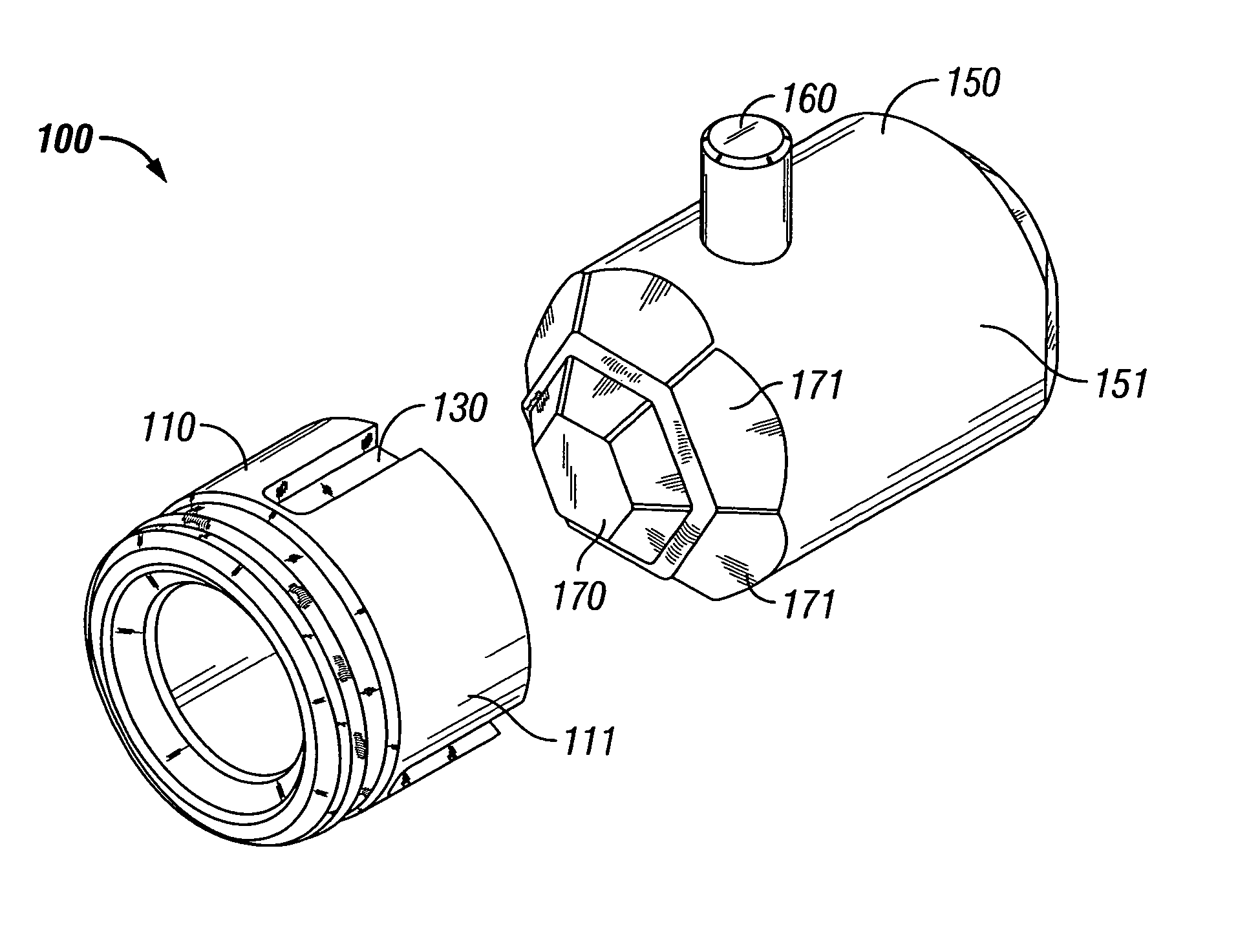
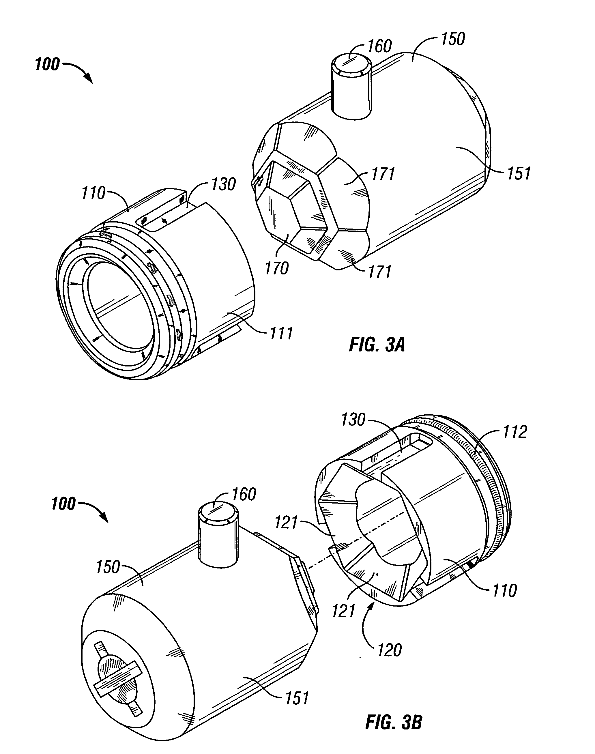
[0033] Referring to FIGS. 3A-3C, an embodiment of the present invention is shown as a gravity valve comprising a plunger 150 and a seat 110. In this embodiment, the plunger 150 has a nose or end 170 having a surface comprising a...


PUM


Abstract

A gravity valve for a downhole tool for use in a subterranean well is described, as is a method of use thereof. The gravity valve is adapted to control the flow of a downhole fluid through the downhole tool. The gravity valve typically includes a plunger and a seat. The plunger may embody a substantially non-spherical end that is adapted to mate with a complementary receiving end on the seat. The increase surface area of contact between the plunger and the seat acts to improve the seal therebetween, reduce the stresses thereon, and improve the performance of the gravity valve in general. The components of the gravity valve may be constructed of materials, which are selected based on the specific gravity of the materials in comparison with the specific gravity of the downhole fluid for a given application. A method of constructing and utilizing the gravity valve is disclosed.

Description

BACKGROUND OF THE INVENTION [0001] 1. Field of the Invention [0002] This invention relates generally to downhole tools for drilling and completing subterranean wells and methods of using these tools; more particularly, this invention relates to downhole tools for selectively providing fluid communication therethrough, and methods of using those tools. [0003] 2. Description of Related Art [0004] In many drilling, servicing, and completion applications, it becomes necessary to isolate particular zones within the well. When it is desired to completely plug a casing downhole, for example, a bridge plug may be utilized, such as those disclosed in U.S. Patent Application Ser. No. 10 / 658,979, entitled “Drillable Bridge Plug” by Lehr et al., incorporated by reference in its entirety herein, and assigned to the same assignee of the present application. [0005] In some situations, it is desirable to provide a tool downhole, which allows fluid to flow in only one direction. For instance, when f...

Claims


Application Information

Patent Timeline
IPC IPC(8): E21BE21B33/00E21B33/12E21B33/13E21B33/134E21B34/06E21B34/08F16K1/50F16K17/12F16K31/30
CPCE21B33/12E21B34/08E21B33/134E21B34/06F16K1/50
Inventor LEHR, DOUGLAS J.
Owner BJ SERVICES CO
Why Eureka
Try Eureka