Connector device for pipes

a technology of connecting device and pipe, which is applied in the direction of fluid pressure sealing joints, pipe elements, couplings, etc., to achieve the effect of optimum sealing function, good sealing action and favorable shap

Inactive Publication Date: 2005-11-24
VOSS AUTOMOTIVE
View PDF5 Cites 12 Cited by
  • Summary
  • Abstract
  • Description
  • Claims
  • Application Information

AI Technical Summary

Benefits of technology

[0005] According to the invention, the above objects are achieved by the insert part consisting of a first, relatively hard and dimensionally stable plastic material and by the dirt seal, consisting of a second, relatively soft and elastic plastic material, being molded directly onto it as a single piece with a cohesive material joint. This advantageous configuration makes it possible for the dirt seal to be designed specifically in terms of shape and / or material to provide an optimum sealing function. For example, use can be made of a soft and elastic material which is optimally suitable for the seal, and it is also possible for favorable shapes, in particular bead-like annular cross sections to be realized, as a result of which a good sealing action is obtained when resting on the circumference of the pipeline. In addition, this configuration also permits an easy pushing-in and, if appropriate, pulling-out of the pipeline because, in contrast to lip seals, in the case of bead seals relative pushing movements cannot result in damaging deformations of the seal. The insert part itself can be designed for optimum mechanical properties through the selection of a suitable material, this being of significance in particular for the supporting of the clamping ring. However, the insert part according to the invention can nevertheless be produced cost effectively in a two-component injection molding process.

Problems solved by technology

The completely recessed arrangement of the insert part within the base part results in a very compact constructional form without protruding parts which could otherwise result in practical use in collisions with other parts in the region surrounding the connecting device or even—in the case of a releasable configuration of the insert part—to an unintentional release of the pipeline.

Method used


Image

  • Connector device for pipes
  • Connector device for pipes
  • Connector device for pipes

Examples


Embodiment Construction

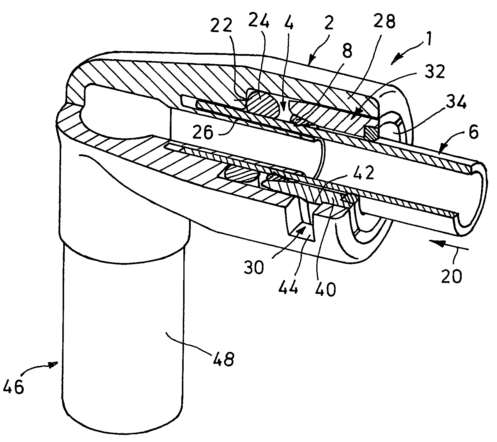
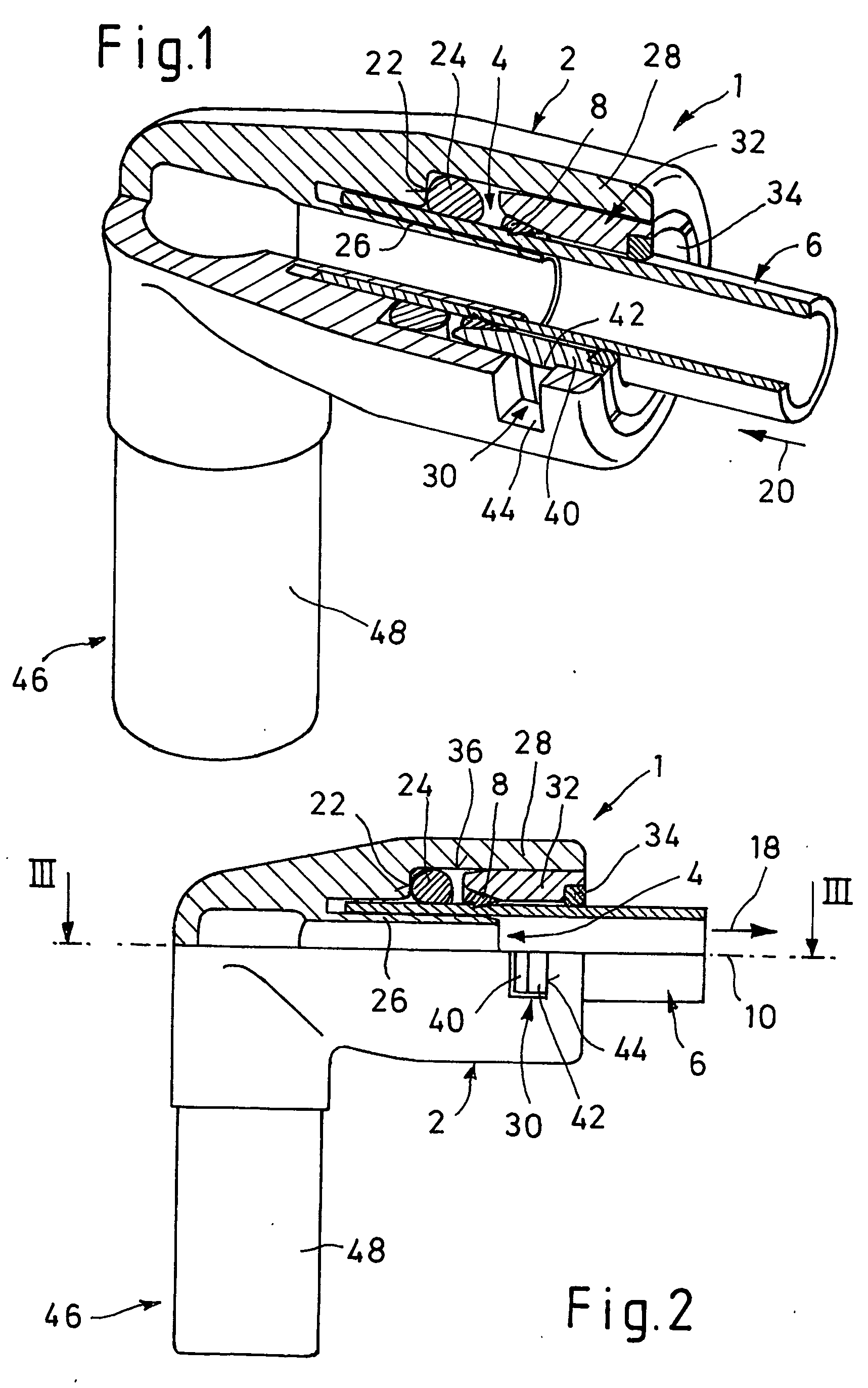
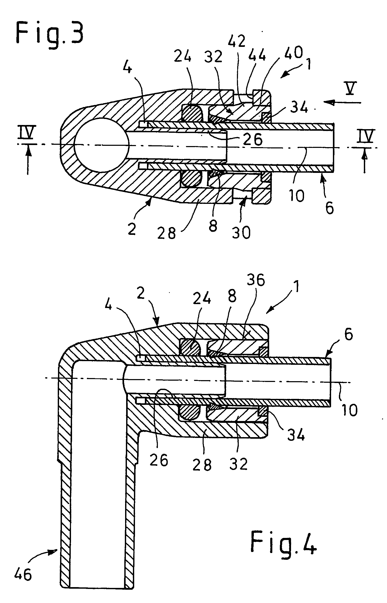
[0036] In the various figures of the drawing, identical parts are always provided with the same reference numbers, so that every description of a part which may appear only once with reference to a certain figure of the drawing also applies analogously to the other figures of the drawing in which the part with the corresponding reference number can likewise be seen.

[0037] In all of the exemplary embodiments, a connecting device 1 according to the invention comprises a housing part 2 with a receiving opening 4, which is open on one side, for the axial insertion of an end of a pipeline 6, and of a clamping ring 8, which is arranged in the housing part 2 or in the receiving opening 4 and is intended for locking the pipeline 6, which is inserted axially, i.e. in the direction of a plug-in axis 10, in place. In this case, the connecting device 1 permits a simple and rapid installation of the pipeline 6, which consists in particular of plastic, by simple insertion into the housing part 2...


PUM

PropertyMeasurementUnit
undercut angleaaaaaaaaaa
elasticaaaaaaaaaa
softaaaaaaaaaa

Abstract

A connecting device for a plug-in connection of at least one pipeline having a housing part having at least one receiving opening for the insertion of the pipeline. A clamping ring is arranged in the receiving opening and, in order to lock the pipeline in place, interacts with an inner one of the housing part. The housing part is made in two parts including a base part and an insert part, which is connected to the base part via a snap-in action forming-fitting connection. The insert part has a direct seal for resting on the circumference of the inserted pipeline. The insert part is formed of a first relatively hard and dimensionally stable plastic material, and has a dirt seal consists of a second, relatively soft and elastic plastic material and is molded directly into the first material as a single piece with a cohesive material joint therebetween.

Description

CROSS REFERENCE TO RELATED APPLICATIONS [0001] This application claims Priority to DE 202 14 847.5, filed Sep. 24, 2002, and PCT / EP03 / 10555, filed Sep. 23, 2003.FIELD OF THE INVENTION [0002] The present invention relates to a connecting device for the plug-in connection of at least one pipeline (pipeline or hose line for gases or liquids). The device includes a housing part having at least one receiving opening for the insertion of the pipeline, and a slotted and, as a result, radially elastically deformable clamping ring, which is arranged in the receiving opening and, in order to lock the pipeline in place, interacts via an outer cone with an inner cone of the housing part. The housing part be is made in two parts from a base part and an insert part, which is connected to the latter via a snap-action form-fitting connection and has the inner cone, and the insert part having a dirt seal for resting on the circumference of the inserted pipeline. BACKGROUND OF THE INVENTION [0003] A ...

Claims


Application Information

Patent Timeline
Patent Type & Authority Applications(United States)
IPC IPC(8): F16L33/22F16L37/092
CPCF16L33/227F16L2201/80F16L37/0925F16L37/008F16L37/0926
Inventor SALOMON-BAHLS, BERND
Owner VOSS AUTOMOTIVE
Why Eureka
Try Eureka