Motor-driven disk brake system

a technology of disk brakes and brake discs, which is applied in the direction of brake cylinders, anti-theft devices, braking systems, etc., can solve the problems of difficult to place the park braking lock mechanism in a locked condition, the unlocked condition of park braking cannot be easily obtained, and the failure of the system to detect the failure of locking/unlocking, etc., to achieve the effect of simple arrangemen

Active Publication Date: 2005-11-24
HITACHI LTD
View PDF8 Cites 35 Cited by
  • Summary
  • Abstract
  • Description
  • Claims
  • Application Information

AI Technical Summary

Benefits of technology

[0009] In view of the situation described, the present invention has been made. It is an object of the present invention to provide a motor-dri

Problems solved by technology

For example, to effect a locking action for park braking, if a plunger of the solenoid malfunctions, it is difficult to place the park braking lock mechanism in a locked condition.
To effect an unlocking action for park braking, if the plun

Method used


Image

  • Motor-driven disk brake system
  • Motor-driven disk brake system
  • Motor-driven disk brake system

Examples


Embodiment Construction

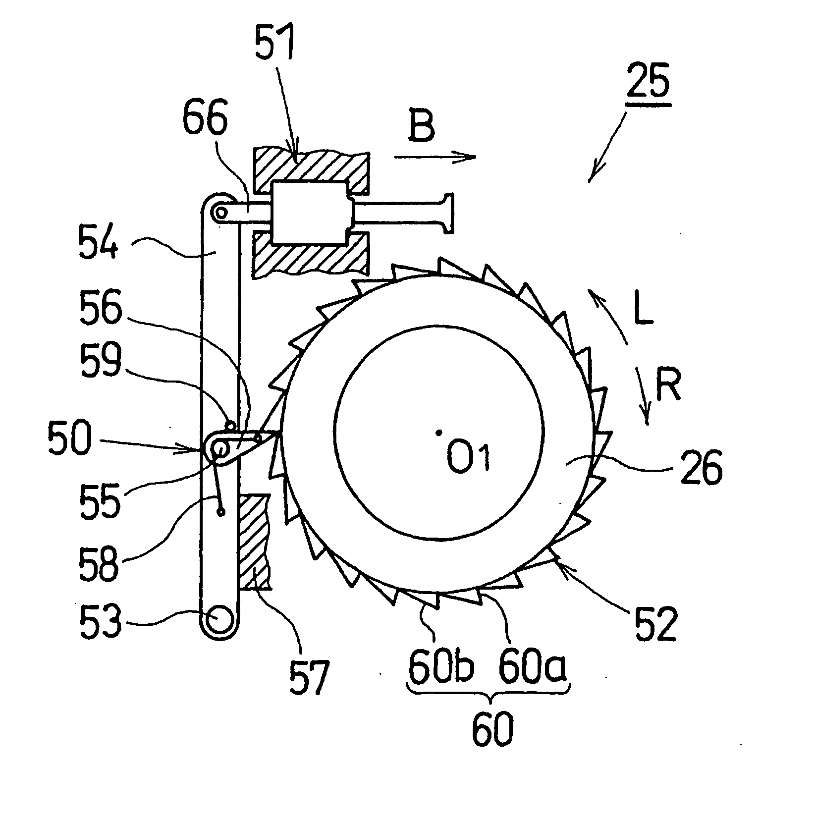
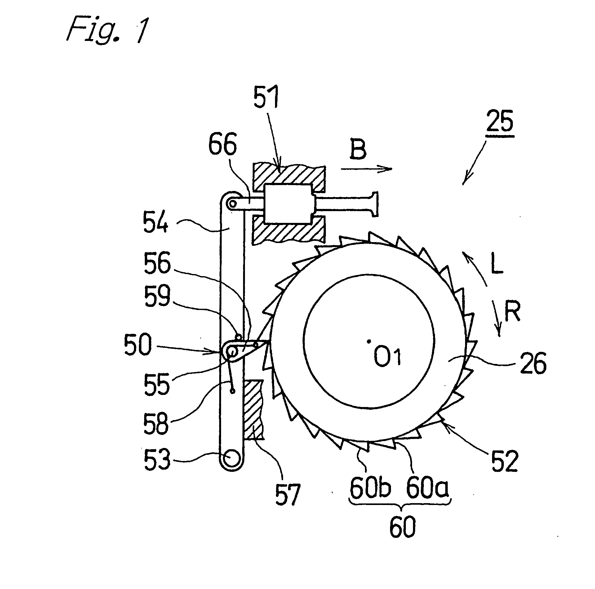
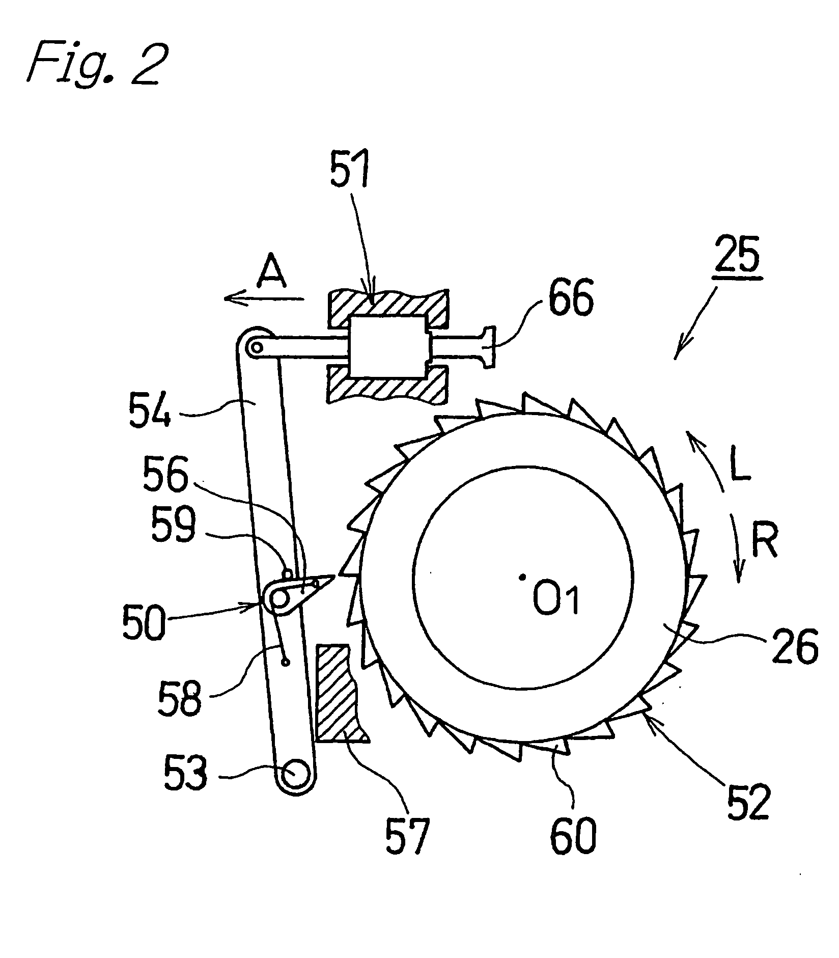
[0040] Referring to the accompanying drawings, a motor-driven disk brake system according to an embodiment of the present invention is described below. In FIG. 4, a motor-driven disk brake system 1 comprises a caliper 4 supported by a carrier 3 that is fixed to a non-rotational portion (such as a knuckle) of a vehicle on an inner side of the vehicle relative to a disk rotor 2. The caliper 4 is supported in a state such that it is capable of a floating movement in an axial direction of the disk rotor 2. A pair of brake pads 5 and 6 are disposed so as to face each other with the disk rotor 2 being provided therebetween. The brake pads 5 and 6 are supported by the carrier 3 in such a manner as to allow movement of the brake pads 5 and 6 in the axial direction of the disk rotor 2.

[0041] The caliper 4 comprises a claw member 9 and a caliper body 10 connected to the claw member 9. The claw member 9 includes a claw portion 7 formed on a forward end thereof and an annular base body 8 forme...


PUM


Abstract

When a solenoid is operated so as to move an engaging pawl to a disengaged position (step S24), if displacement detection means (an angular position sensor and a controller) detects that a motor rotor has not been displaced by an amount equal to or exceeding a predetermined level, that is, if the motor has not returned by an amount equal to or exceeding the predetermined level within a predetermined time period, and the answer in step S26 is NO and the answer in step S27 is YES (the predetermined time period has passed), a defect in an unlocked condition (an unlocking failure of a park braking lock mechanism) is determined (step S28). In this case, a driver is notified of the failure, so that prompt action can be taken to rectify the unlocking failure of the park braking lock mechanism.

Description

BACKGROUND OF THE INVENTION [0001] The present invention relates to a motor-driven disk brake system for generating a braking force by means of a torque of a motor. More specifically, the present invention relates to a motor-driven disk brake system provided with a park braking function. [0002] As an example of a motor-driven disk brake system, there can be mentioned a motor-driven disk brake system comprising a caliper having provided therein a piston, a motor and a rotary-linear motion conversion mechanism for enabling rotation of the motor to be converted to a linear motion and transmitted to the piston. A thrust is imparted to the piston according to rotation of a rotor of the motor, to thereby press a brake pad against a disk rotor, thus generating a braking force. Normally, in this motor-driven disk brake system, a force applied by a driver to a brake pedal, or a stroke of the brake pedal, is detected by a sensor, and rotation (an angle of rotation) of the motor is controlled ...

Claims


Application Information

Patent Timeline
IPC IPC(8): B60T1/00B60T7/00B60T13/66B60T17/18F16D65/14
CPCB60T1/005B60T17/18F16D65/18F16D2129/08F16D2125/36F16D2127/06F16D2121/24
Inventor YAMAGUCHI, TOHMA
Owner HITACHI LTD
Why Eureka
Try Eureka