Gas-discharge display apparatus

Inactive Publication Date: 2005-11-24
PIONEER CORP
View PDF4 Cites 4 Cited by
  • Summary
  • Abstract
  • Description
  • Claims
  • Application Information

AI Technical Summary

Benefits of technology

[0019] At this point, the first phosphor layer has a high resistance to the xenon resonance line in the vacuum ultraviolet light. For this reason, deterioration with time such as that caused by brightness degradation occurs less.
[0020] The deficiency in emission brightness due to the passing-trough of the xenon molecular beam in the vacuum ultraviolet light is made up for by the light emission from the second phosphor layer excited by the xenon molecular beam which has passed through the first phosphor layer. The combined light emission from the first phosphor layer and the second phosphor layer make it possible to ensure the degree o

Problems solved by technology

When the phosphor layer is irradiated for a long time with the high-energy vacuum ultraviolet light, deterioration over time such as that caused by brightnes

Method used


Image

  • Gas-discharge display apparatus
  • Gas-discharge display apparatus
  • Gas-discharge display apparatus

Examples


Example

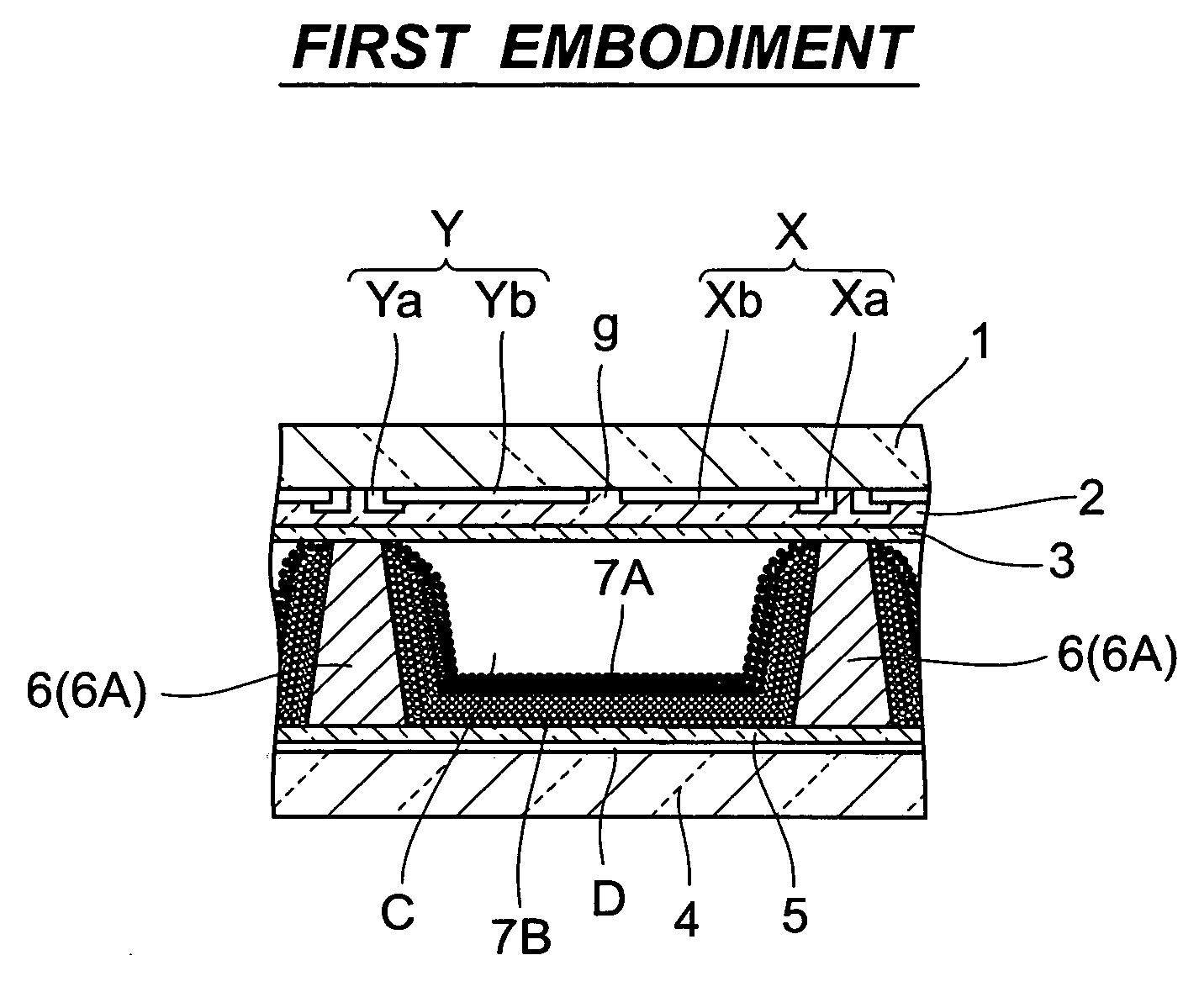
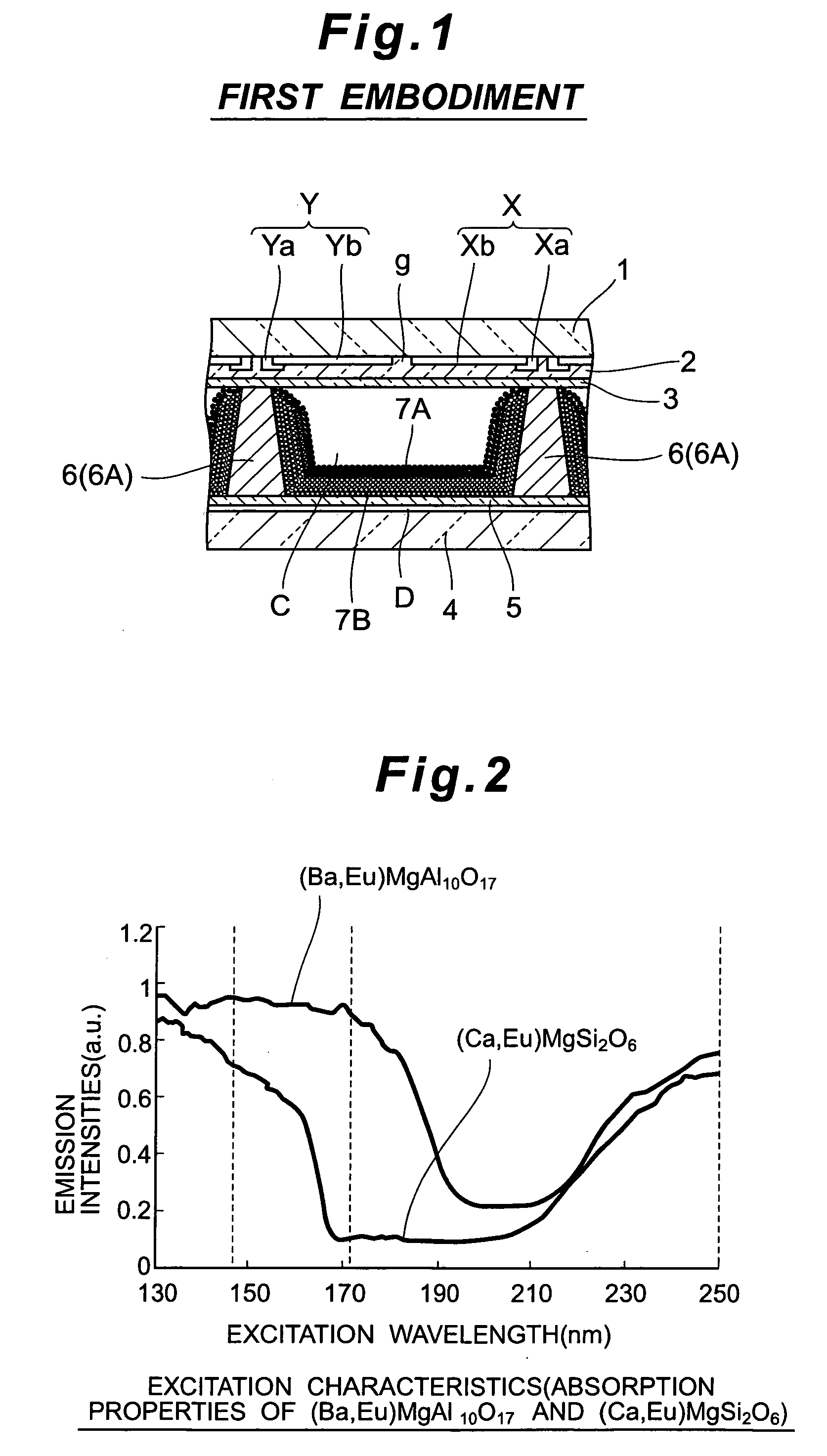
[0027]FIG. 1 is a sectional view illustrating the first embodiment when the gas-discharge display apparatus according to the present invention is applied to a PDP.

[0028]FIG. 1 shows a sectional view of the structure of an area in the PDP surrounding a discharge cell C, cut through the PDP in the column direction.

[0029] In FIG. 1, the PDP has a plurality of row electrode pairs (X, Y) extending in the row direction (the direction at right angles to the right-left direction in FIG. 1) and regularly arranged in the column direction (the right-left direction in FIG. 1) on the rear-facing face of a front glass substrate 1 serving as the display surface.

[0030] Row electrodes X and Y in each row electrode pair (X, Y) are each composed of bus electrodes Xa, Ya extending in a bar shape in the row direction, and transparent electrodes Xb, Yb that are lined up at regular intervals along the associated bus electrodes Xa, Ya. The transparent electrodes Xb and the transparent electrodes Yb each...

Example

Second Embodiment

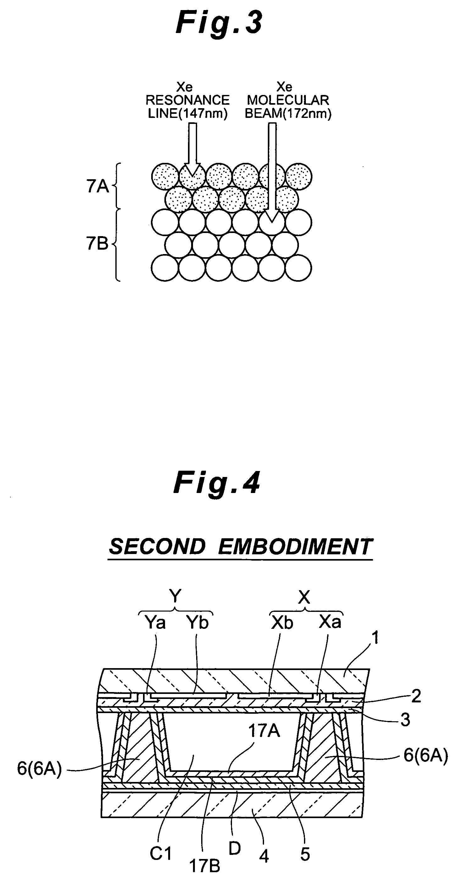
[0047]FIG. 4 is a sectional view illustrating a second embodiment when the gas-discharge display apparatus according to the present invention is applied to a PDP.

[0048]FIG. 4 shows a sectional view of the structure of an area of the PDP surrounding a discharge cell, cut through the PDP in the column direction. The first and second embodiments are the same except for the structure of the phosphor layer. The same structural components are designated by the same reference numerals.

[0049] In FIG. 4, in each discharge cell C1, a phosphor layer covers five faces: the side faces of the transverse walls 6A and the vertical walls of the partition wall unit 6 and the face of the portion of the column-electrode protective layer 5 lying between the transverse walls 6A and the vertical walls. The three primary colors, red, green and blue, are individually applied to the phosphor layers such that the red, green and blue colors in the discharge cells C1 are arranged in order in...


PUM


Abstract

A phosphor layer is provided on a back glass substrate placed opposite a front glass substrate with a discharge space in between, and formed in a double-layer structure consisting of a first phosphor layer and a second phosphor layer having its surface covered by the first phosphor layer. The first phosphor layer is formed of materials that permit the passing-through of a xenon molecular beam but absorb a xenon resonance line in the vacuum ultraviolet light generated from a discharge gas by means of a discharge, and have a higher resistance to the resonance line than that of the second phosphor layer. The second phosphor layer is formed of materials that have, as compared with the first phosphor layer, a higher light-emission brightness based on the xenon molecular beam in the vacuum ultraviolet light generated from the discharge gas by means of the discharge.

Description

BACKGROUND OF THE INVENTION [0001] 1. Field of the Invention [0002] This invention relates to the structure of a phosphor layer provided in a gas-discharge display apparatus for generating visible light. [0003] The present application claims priority from Japanese Application No. 2004-147648, the disclosure of which is incorporated herein by reference. [0004] 2. Description of the Related Art [0005] In a typical structure of a plasma display panel (hereinafter referred to as “PDP”) which is a type of gas-discharge display apparatus, a pair of opposing substrates is placed on both sides of a discharge space. Row electrode pairs, a dielectric layer covering the row electrode pairs, and a protective layer covering the dielectric layer are formed on the inner face of one of the substrates. Column electrodes, a column-electrode protective layer covering the column electrodes and red-, green- and blue-colored phosphor layers are formed on the inner face of the other substrate. The column ...

Claims


Application Information

Patent Timeline
IPC IPC(8): C09K11/77H01J11/12H01J11/22H01J11/24H01J11/26H01J11/34H01J11/42H01J61/44H01J61/48
CPCC09K11/7734H01J11/12H01J11/42C09K11/77342
Inventor AKIYAMA, KAZUYASUGIO, YUKIHIKOHIBINO, YO
Owner PIONEER CORP
Why Eureka
Try Eureka