
Permanent magnet for particle beam accelerator and magnetic field generator

a technology of permanent magnets and accelerators, applied in the field of permanent magnets, can solve the problems of large current needs to be supplied, damage to respective members, and joule heat generated by coils

Inactive Publication Date: 2005-11-24
HITACHI METALS LTD
View PDF6 Cites 13 Cited by
  • Summary
  • Abstract
  • Description
  • Claims
  • Application Information

AI Technical Summary

Benefits of technology

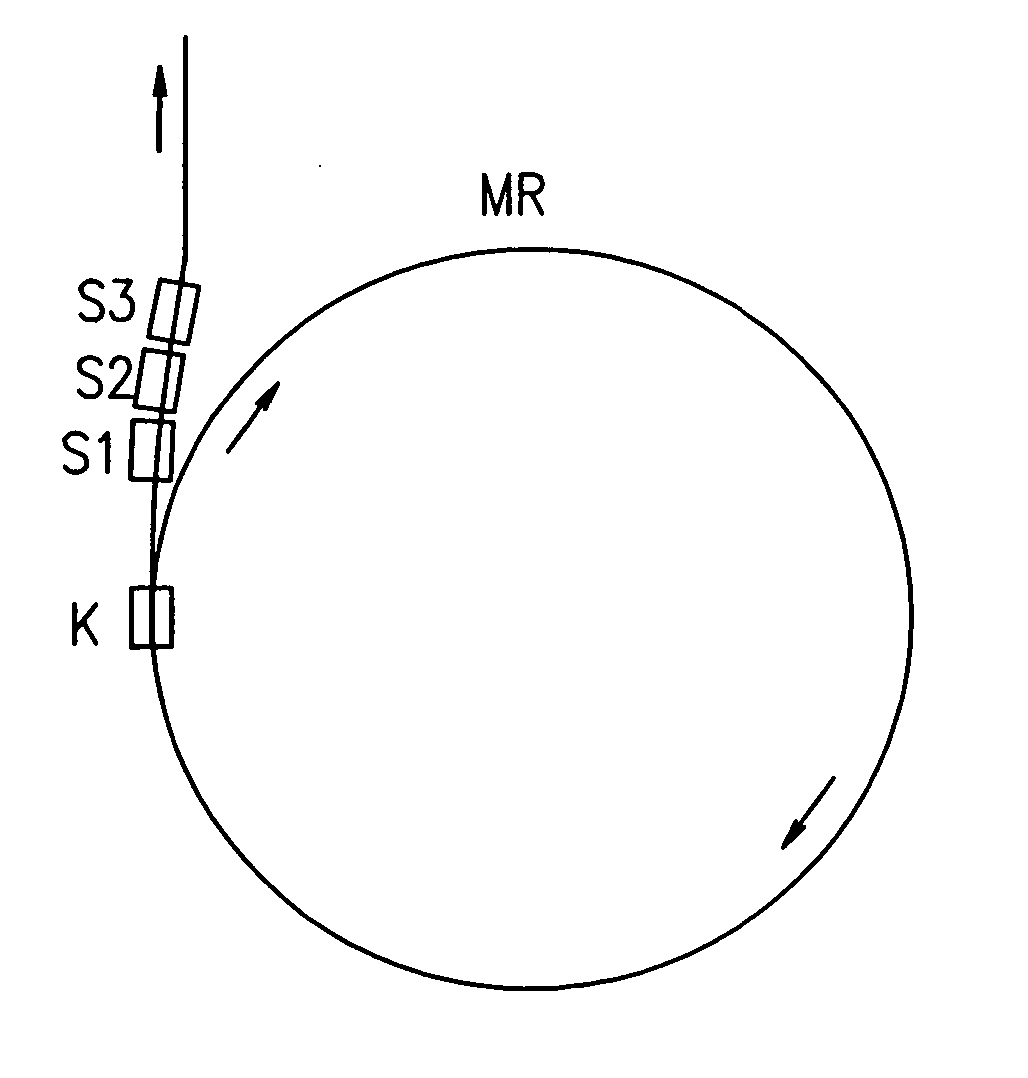
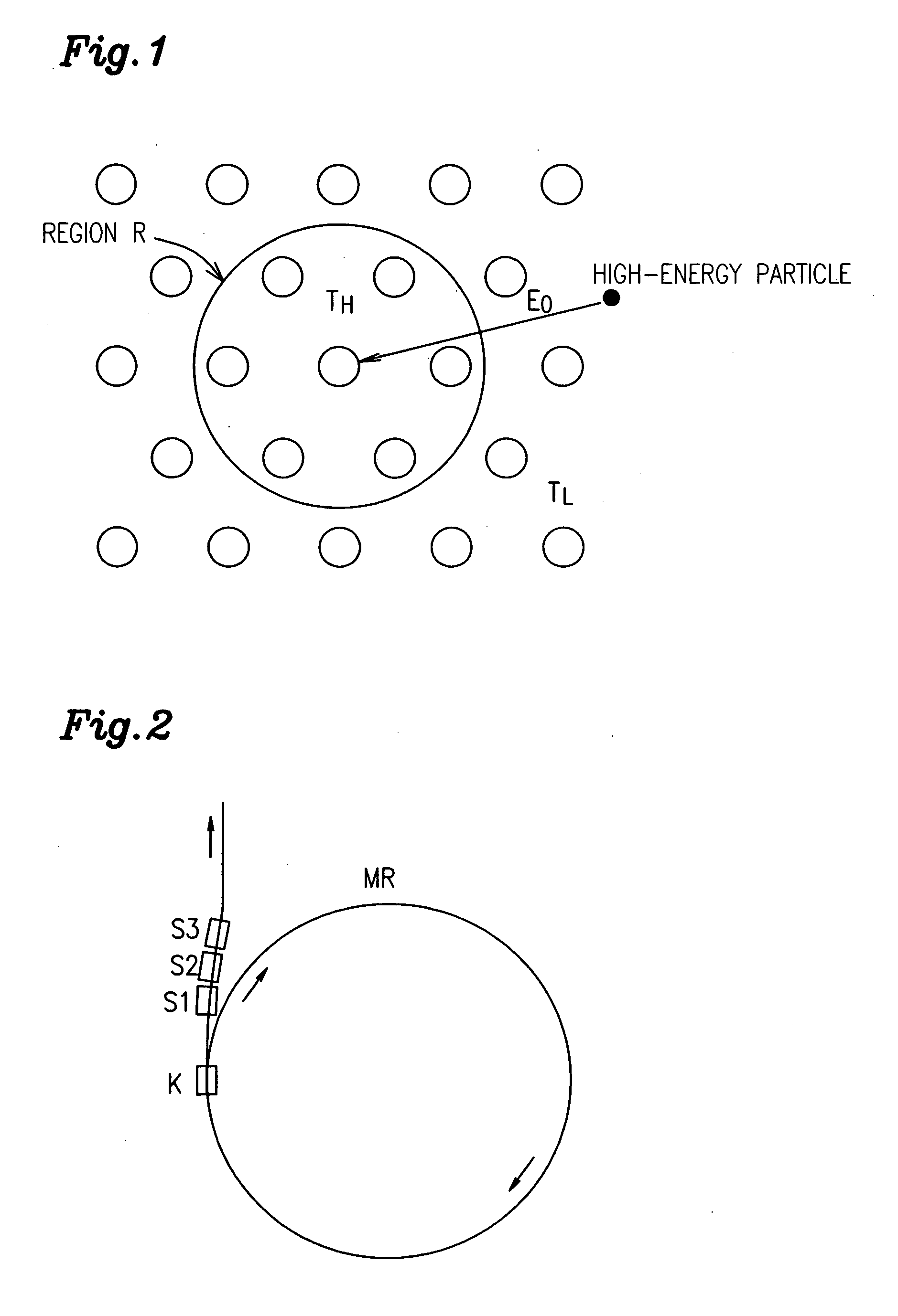
[0021] A permanent magnet for a particle accelerator according to the present invention is used in an environment in which the magnet is exposed to a radiation at an absorbed dose of at least 3,000 Gy. The magnet includes R (which is at least one of the rare-earth elemen

Problems solved by technology

Thus, during the operation, a large amount of current needs to be supplied to the coil of the electromagnet.
However, when a large amount of current is supplied to the coil, a lot of Joule heat is generated by the coil.
Furthermore, when an electromagnet is used, the strong magnetic field that is generated intermittently by the electromagnet easily does damage on respective members that form the electromagnet, which is also a problem.
In addition, a huge quantity of yoke material for use to make the electromagnet is mainly composed of iron, and therefore, is easily radioactivated when exposed to the radiation generated from the beam line.
If the yoke material is radioactivated, then it becomes difficult for workers to access the electromagnets for maintenance purposes.
However, hard ferrite cannot generate a strong bending magnetic field (e.g., of about 2 T) if its size remains small.
Thus, it would be impossible to use small-sized particle accelerators in general hospitals extensively.
Thus, considering maintenance, it would also be difficult to adopt those magnets in the accelerator.
Once demagnetized in this manner, the magnet can no longer generate a strong magnetic field constantly.

Method used


Image

  • Permanent magnet for particle beam accelerator and magnetic field generator
  • Permanent magnet for particle beam accelerator and magnetic field generator
  • Permanent magnet for particle beam accelerator and magnetic field generator

Examples


example 1

[0071] First, an R-TM-B based material powder, having a composition including Nd, Dy, B, Fe and inevitably contained impurity elements as shown in the following Table 1, was prepared. The powder had a mean particle size of 3.0 μm. This powder was compacted under a magnetic field and then sintered at 1,060° C. for 4 hours within a vacuum, thereby obtaining a sintered magnet material. A sample piece was taken from the sintered magnet material, magnetized and then its magnetic properties were measured at room temperature. The results are shown in the following Table 2, which additionally shows the Curie temperature (Tc) of each sintered magnet material.

TABLE 1Magnet composition (mass %)No.NdDyBFeExamples121.010.01.0Balance223.57.51.0Balance326.05.01.0BalanceComparative428.52.51.0BalanceExamples531.0—1.0Balance

[0072]

TABLE 2CurieBrHcJ(BH)maxtemperatureNo.(T)(MA / m)(kJ / m3)(° C.)Examples11.152.425531621.212.027931631.261.6303316Comparative41.331.3342318Examples51.390.9374316

[0073] Next, t...

example 2

[0080] First, an R-TM-B based material powder, having a composition including Nd, Dy, B, Fe and inevitably contained impurity elements and having a mean particle size of 3.0 μm, was prepared. This powder was compacted under a magnetic field and then sintered at 1,060° C. for 4 hours within a vacuum, thereby obtaining a sintered magnet material having a composition including 28.5 mass % of Nd, 2.5 mass % of Dy, 1.0 mass % of B, 1.0 mass % of Co, and Fe as the balance. A sample piece was taken from each of these sintered magnet materials, magnetized and then its magnetic properties were measured at room temperature. The resultant magnetic properties included a Br of 1.33 T, an HcJ of 1.3 MA / m and a (BH)max of 342 kJ / m3.

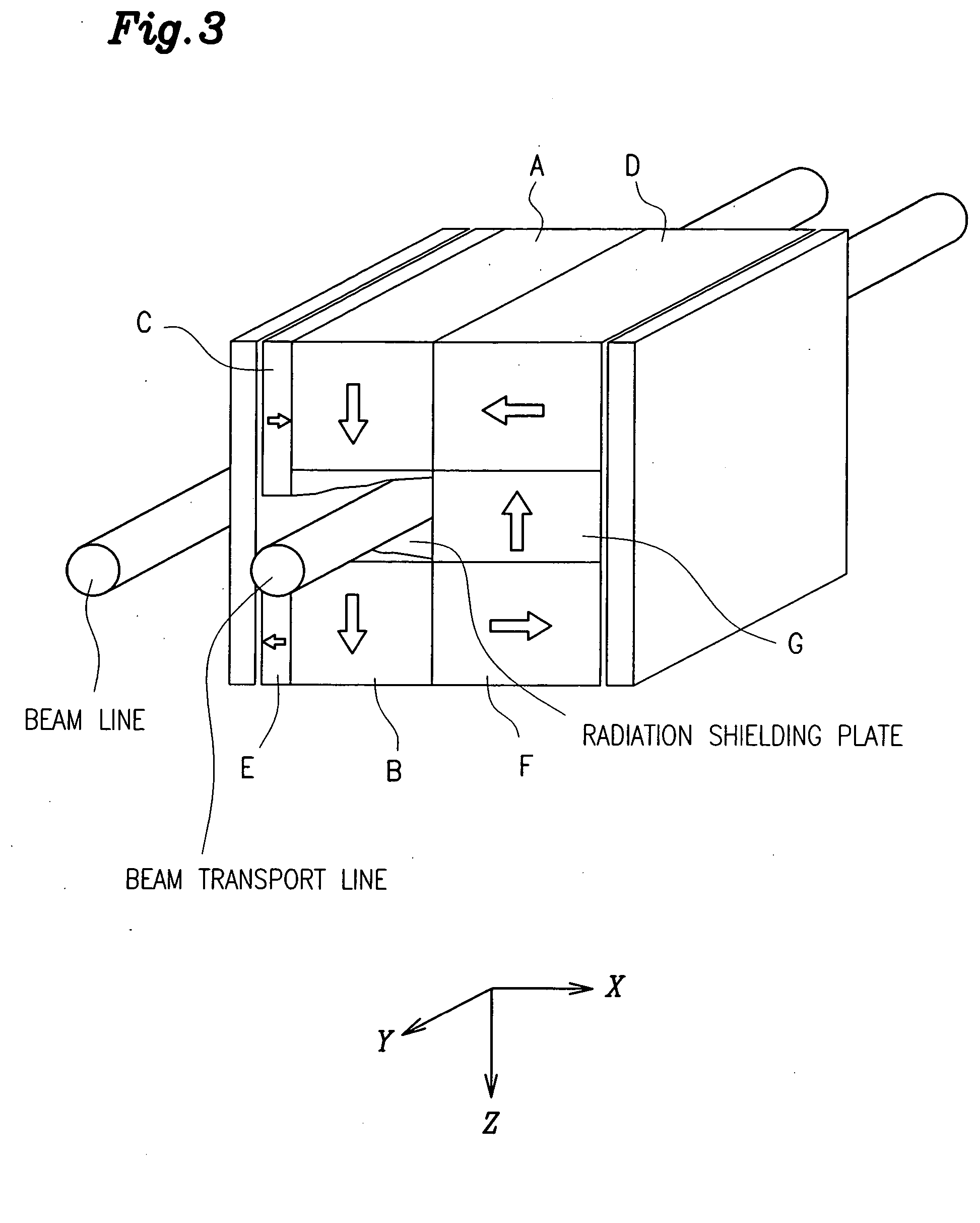
[0081] Next, the resultant sintered magnet material was machined to obtain rectangular parallelepiped magnets. Then, those magnets were magnetized. A magnetic field generator having the configuration shown in FIG. 3 was assembled of the magnetized rectangular parallele...


PUM

PropertyMeasurementUnit
Percent by massaaaaaaaaaa

Abstract

A permanent magnet for a particle accelerator and a magnetic field generator, in which Nd—Fe—B based magnets are used but are not demagnetized so easily even when exposed to a radiation, are provided. A permanent magnet for a particle accelerator is used in an environment in which the magnet is exposed to a radiation at an absorbed dose of at least 3,000 Gy. The magnet includes R (which is at least one of the rare-earth elements), B, TM (which is at least one transition element and includes Fe) and inevitably contained impurity elements. The magnet is a sintered magnet that has been magnetized to a permeance coefficient of 0.5 or more and that has a coercivity HcJ of 1.6 MA / m or more.

Description

BACKGROUND OF THE INVENTION [0001] 1. Field of the Invention [0002] The present invention relates to a permanent magnet for use in an environment in which the magnet is exposed to a radiation at an absorbed dose of 3,000 Gy or more. More particularly, the present invention relates to a permanent magnet for a particle accelerator, which may be used in either a synchrotron for the purpose of physical properties research or a cyclotron in the field of radiotherapy. The present invention also relates to a magnetic field generator including a plurality of such magnets. [0003] 2. Description of the Related Art [0004] Examples of particle accelerators includes a synchrotron, which is used to generate a high-energy particle beam for the purpose of physical properties research, and a small-sized cyclotron, which produces a radioisotope for use in the diagnosis of cancer. Recently, those accelerators have just been introduced into a sort of radiotherapy for directly irradiating the diseased p...

Claims


Application Information

Patent Timeline
IPC IPC(8): H01F1/057H01F7/02H05H7/04
CPCB22F2003/242B22F2003/248B22F2998/00B22F2998/10H05H7/04C22C33/0278C22C2202/02H01F1/0577H01F7/0278B22F2999/00B22F3/1007B22F2201/20B22F9/04B22F3/02B22F3/24B22F2202/05
Inventor MAKITA, KENSUGIYAMA, EIJIAOKI, MASAAKIMURAKAMI, KAICHIKAWAKUBO, TADAMICHINAKAMURA, EIJI
Owner HITACHI METALS LTD
Learn More