Drive regenerative control system

a regenerative control and drive technology, applied in the direction of dynamo-electric converter control, electric generator control, magnetic circuit shape/form/construction, etc., can solve the problems of inability to control the torque of electric motors in multi-stage or linear ways, and the weight became massive in comparison to the generated torque, so as to achieve the effect of superior torque and weight balan

Inactive Publication Date: 2005-11-24
PARKSIDE IP LLC
View PDF13 Cites 19 Cited by
  • Summary
  • Abstract
  • Description
  • Claims
  • Application Information

AI Technical Summary

Benefits of technology

[0009] Nevertheless, with the motor explained in the description of the related art, the weight became massive in comparison to the generated torque, and there is a problem in that the motor would become enlarged when attempting to increase the generated torque. Further, with the conventional technology, it is not possible to control the electric motor torque in multi stages or linearly. Thus, an object of the present invention is to provide a system employing a motor suitable for miniaturization and superior in torque and weight balance for the drive control and regenerative control of the drivee. Moreover, the present invention provides a system enabling the multistage or linear control of the electric motor torque to be used for driving the drivee.
[0010] In order to achieve the foregoing objects, the present invention provides a drive regenerative control system, comprising: a drive system for driving a drivee in which an electric motor is combined with another drive source as necessary; a mechanism for transmitting the driving force from the drive system to the drivee; an electric motor operation control circuit for controlling the drive and regeneration of the electric motor; a storage mechanism for storing regenerative energy; a storage control circuit; a sensor for detecting the motion of the drivee; and an operation control device for outputting a drive control signal to the electromotive drive system based on the sensor output; wherein the electric motor has a movable body constituted from a magnetic body, and a plurality of phase coils, and the operation control device controls one or a plurality of the phase coils for driving and / or regeneration according to the operation status of the drivee.
[0011] In an embodiment of the present invention, the other drive source is an internal combustion, the drivee is a running vehicle, and a plurality of the storage mechanisms is provided. Further, the storage control circuit selects a mechanism suitable for charging with regenerative energy, and charges the storage mechanism with the regenerative energy. Moreover, the motor establishes a stator by forming a plurality of phase coils with a plurality of coil arrays to be excited at alternate opposite poles in relation to a rotor as the movable body formed by continuously disposing a plurality of permanent magnets magnetized at alternate opposite poles, disposes the stator without contacting the rotor, and rotates the rotor by supplying to the coils a pulse signal wave having a frequency.
[0012] Further, when the drivee is running on a low load, the operation control device performs control so as to simultaneously use a part of the a plurality of phase coils for driving and the other phase coils for regeneration. The electric motor operation control circuit has a comparison circuit for comparing the detection signal and reference signal obtained based on the sensor output, forms a drive control signal of the electric motor of the electric motor based on the comparison result and supplies this to the drive circuit of the electric motor, and further forms the regenerative control signal based on the comparison result and supplies this to the storage control unit. The comparison circuit compares the phase of the detection signal and reference signal, and the drive control signal or regenerative control signal is formed based on the phase difference. The electric motor operation control circuit determines the duty ratio of the drive signal of the electric motor to be supplied to the drive circuit based on the phase difference, and determines the duty ratio of the regenerative enabling signal to be supplied to the storage control unit based on the phase difference. The combination of the phase coils to be drive controlled or regenerative controlled according to the operation status of the drivee is formed into a table and stored in the memory, and the operation control circuit refers to the memory to determine the phase coils to be excited based on the sensor output.
[0013] In addition, a magnetic sensor is further provided in relation to the movable body for each of the phase coils, and the electric motor operation control circuit determines the hysteresis level in relation to the output of the magnetic sensor based on the comparison result, and determines the duty ratio from the hysteresis level and the magnetic sensor output. The output of the sensor is directly supplied to the phase coils as an excitation current.

Problems solved by technology

Nevertheless, with the motor explained in the description of the related art, the weight became massive in comparison to the generated torque, and there is a problem in that the motor would become enlarged when attempting to increase the generated torque.
Further, with the conventional technology, it is not possible to control the electric motor torque in multi stages or linearly.

Method used


Image

  • Drive regenerative control system
  • Drive regenerative control system
  • Drive regenerative control system

Examples


Embodiment Construction

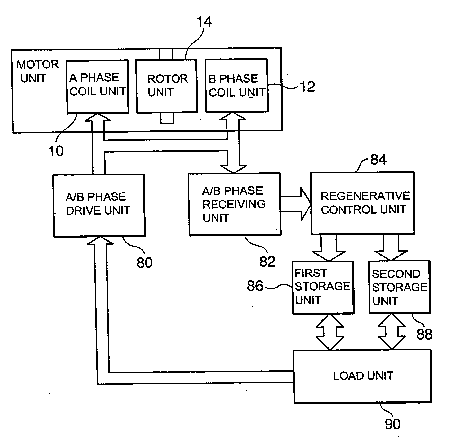
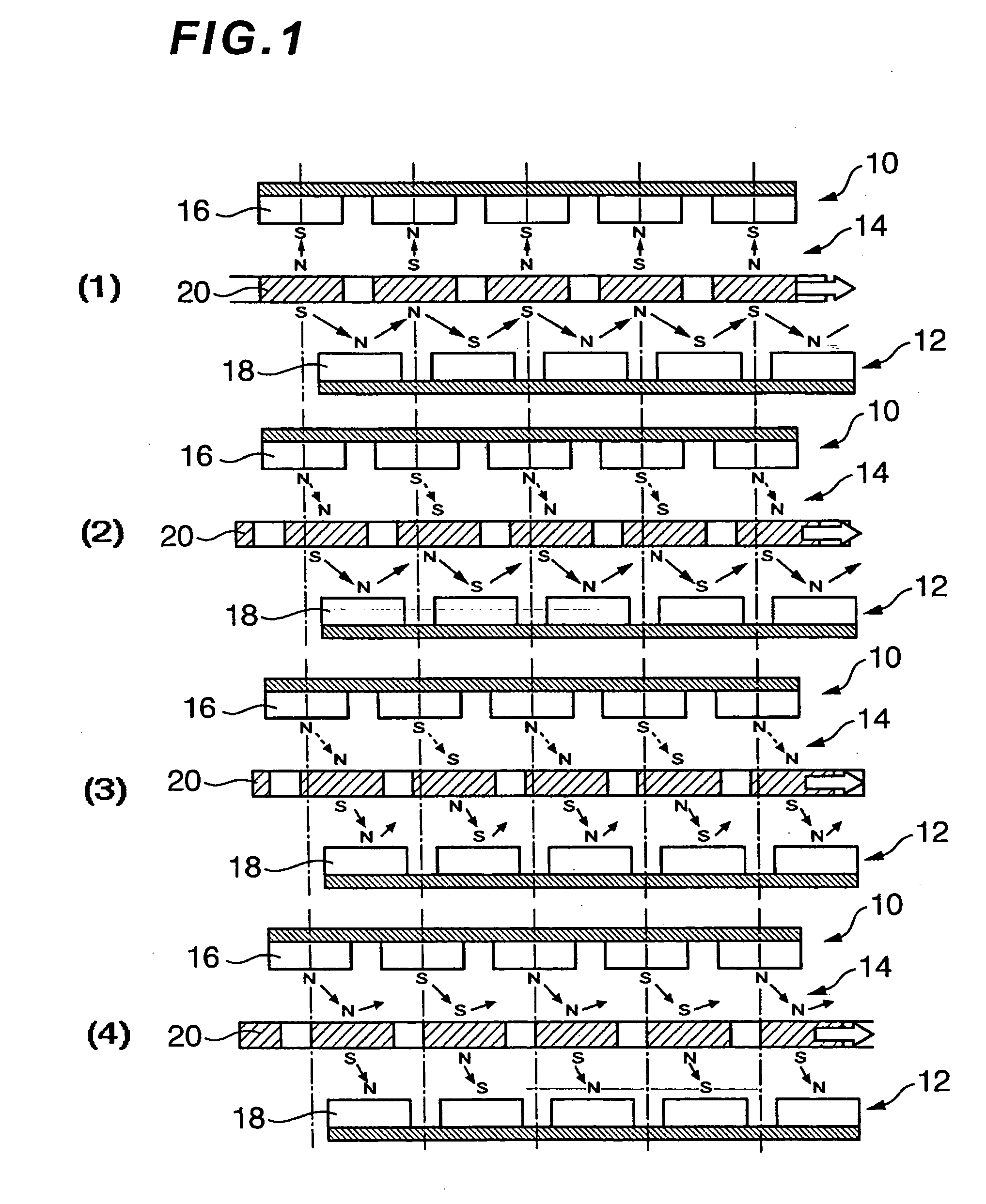
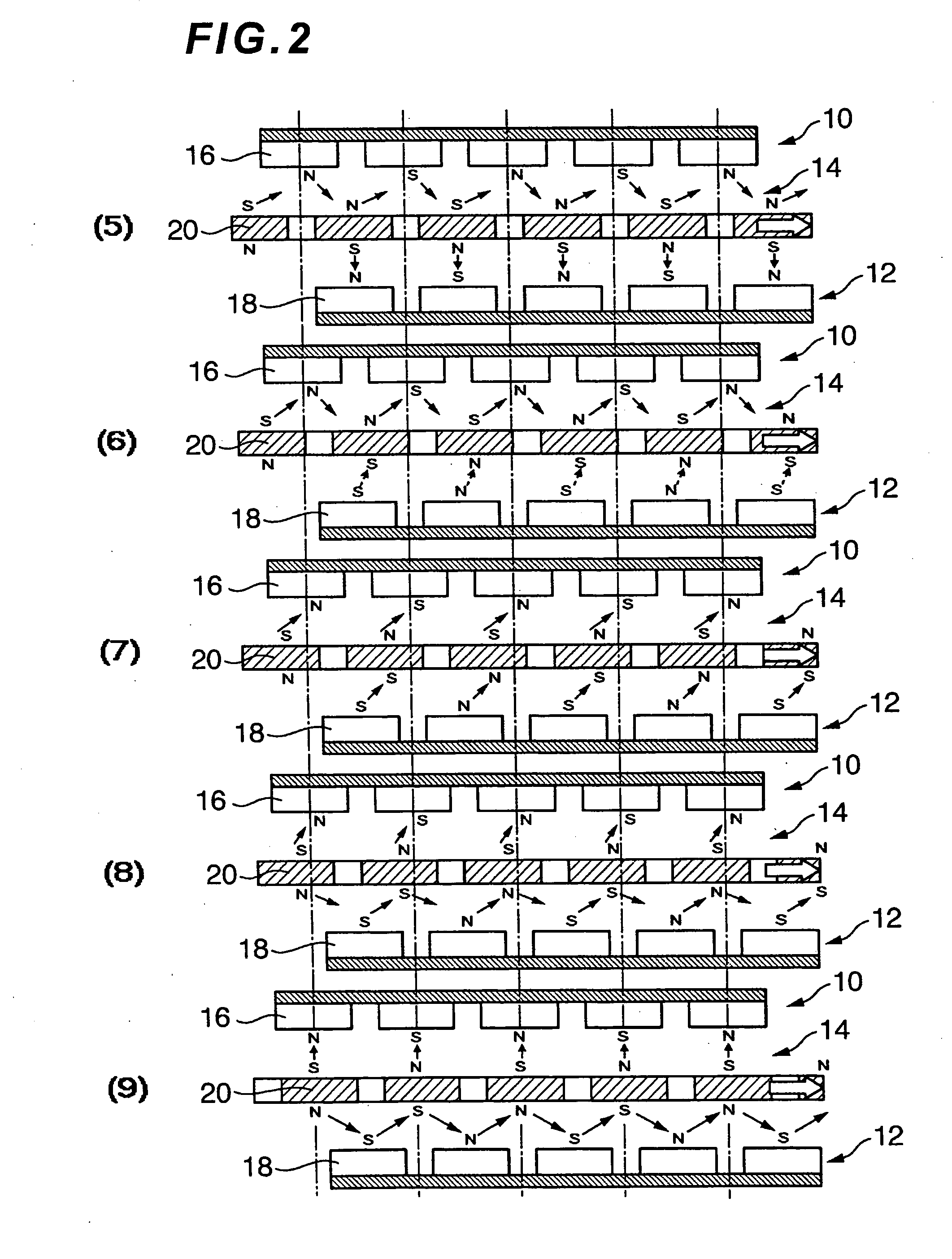
[0048]FIG. 1 and FIG. 2 are diagrams showing the principal of operation of a representative motor pertaining to the present invention. This motor has a constitution where a third permanent magnet 14 is interposed between a first coil pair (A phase coil) 10 and a second coil pair (B phase coil) 12. The coils and permanent magnet may be constituted circularly (arc, circle) or linearly. When formed circularly, either the permanent magnet or the coil phase functions as the rotor, and, when formed linearly, one of the above becomes a slider.

[0049] The first coil pair (phase coil) 10 comprises a constitution in which the coils 16 alternately excitable to the opposite poles are sequentially aligned in a prescribed spacing, preferably an even spacing. FIG. 5 is an equivalent circuit diagram of this first coil pair. According to FIG. 1 and FIG. 2, as described later, with a two-phase excitation coil, all coils are excited to be constantly driven against the two-phase exciting coil during th...


PUM


Abstract

Provided is a drive regenerative control system of a drivee with a motor superior in torque and weight balance and suitable for miniaturization as the drive source. In a drive regenerative control system having a drive source with an electric motor, a drivee, a control circuit having a drive control circuit of the motor and a regenerative control circuit, and a detection unit for detecting the driving status of the drivee, the drive control circuit and regenerative control circuit have a control unit for controlling, linearly or in multiple stages, the duty ratio of the drive or regenerative signal to be supplied to the motor based on the phase difference of the phase of the detection signal from the detection unit and the command value signal to the motor.

Description

BACKGROUND OF THE INVENTION [0001] 1. Field of the Invention [0002] The present invention relates to a drive regenerative control system for driving a drivee by employing an electric motor as the drive source. As the drivee, considered may be an automobile, aircraft, ship and so on. The present invention also relates to a drive regenerative control system in a hybrid system simultaneously using an internal combustion and electric motor. [0003] 2. Description of the Related Art [0004] Conventionally, as this type of drive control system, for instance, there is a drive control system described in the gazette of WO 02 / 087066 (Patent Document 1). This drive control device for controlling the electromotive rotation drive unit for moving a driver comprises a reference comparative signal generation circuit, a detection circuit for detecting the speed of the driver and outputting this as a detection signal, a speed designation circuit of the driver, a rotation control circuit of the driver,...

Claims


Application Information

Patent Timeline
Patent Type & Authority Applications(United States)
IPC IPC(8): B60K6/26B60L50/13B60L50/16B60W10/08B60W20/00H02P8/24H02P9/04
CPCB60K6/26B60K6/28Y02T10/70Y02T10/7077B60L11/08B60L50/13Y02T10/7072
Inventor TAKEUCHI, KESATOSHI
Owner PARKSIDE IP LLC
Why Eureka
Try Eureka