
Ferroelectric memory and method for reading data from the ferroelectric memory

Inactive Publication Date: 2005-11-24
PANASONIC CORP
View PDF9 Cites 7 Cited by
  • Summary
  • Abstract
  • Description
  • Claims
  • Application Information

AI Technical Summary

Benefits of technology

[0036] Specifically, a ferroelectric memory of the present invention comprises: a plurality of normal cells, each of which includes a first ferroelectric capacitor for holding data and a first transistor connected to a first electrode of the first ferroelectric capacitor; a first bit line connected to the first transistor; a first bit line precharge circuit which is a switch circuit provided between the first bit line and a ground; and a word line connected to a gate of the first transistor, wherein the word line is deactivated to disconnect the first ferroelectric capacitor from the first bit line before the first bit line precharge circuit is driven to discharge a potential of the first bit line. According to the ferroelectric memory of the present invention, even when the first bit line is discharged at a high speed, the potential of the first electrode of the first ferroelectric capacitor does not change. Thus, undershoot noise is not caused in the cell plate line. Therefore, since the discharge of the first bit line is executed at a high speed, the cycle time is shortened. As a result, a highly-reliable, high-speed ferroelectric memory is realized.
[0048] According to a ferroelectric memory of the present invention, in the process of discharging a bit line, corruption of data stored in a normal cell is prevented, and the cycle time is shortened. Thus, a highly-reliable, high-speed ferroelectric memory is realized.

Problems solved by technology

Therefore, there is a possibility that stored data is corrupted.
Thus, the noise caused in the cell plate line deteriorates the nonvolatility of the ferroelectric memory and therefore greatly deteriorates the reliability of the ferroelectric memory.
However, if the speed of discharging the bit line is decreased, the cycle time of the ferroelectric memory becomes longer, and the operation speed of the memory decreases.

Method used


Image

  • Ferroelectric memory and method for reading data from the ferroelectric memory
  • Ferroelectric memory and method for reading data from the ferroelectric memory
  • Ferroelectric memory and method for reading data from the ferroelectric memory

Examples


embodiment 1

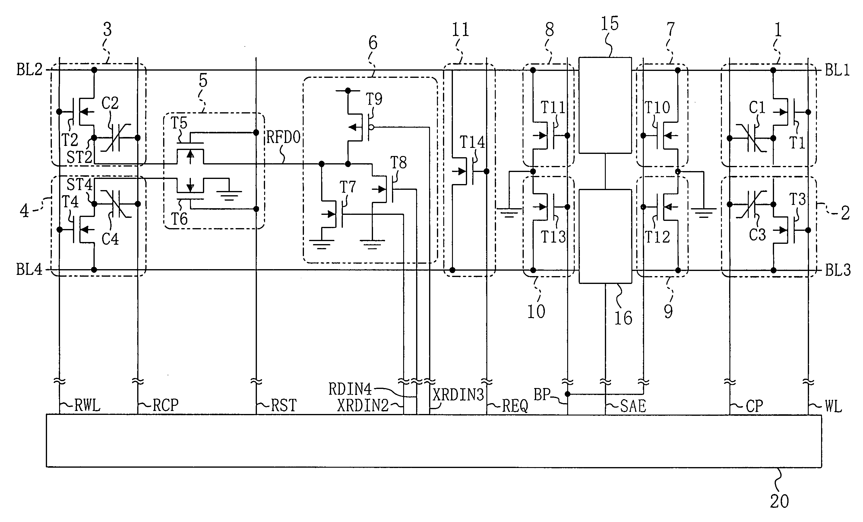
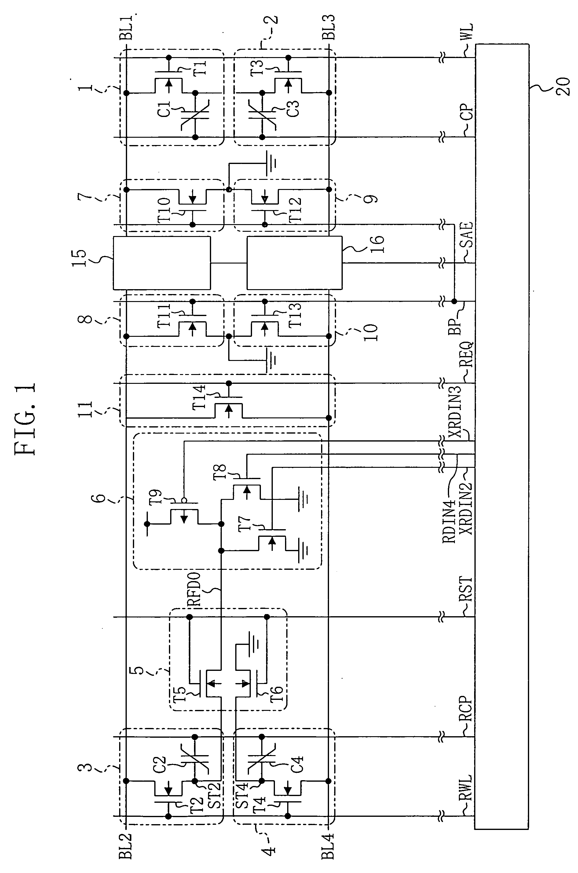
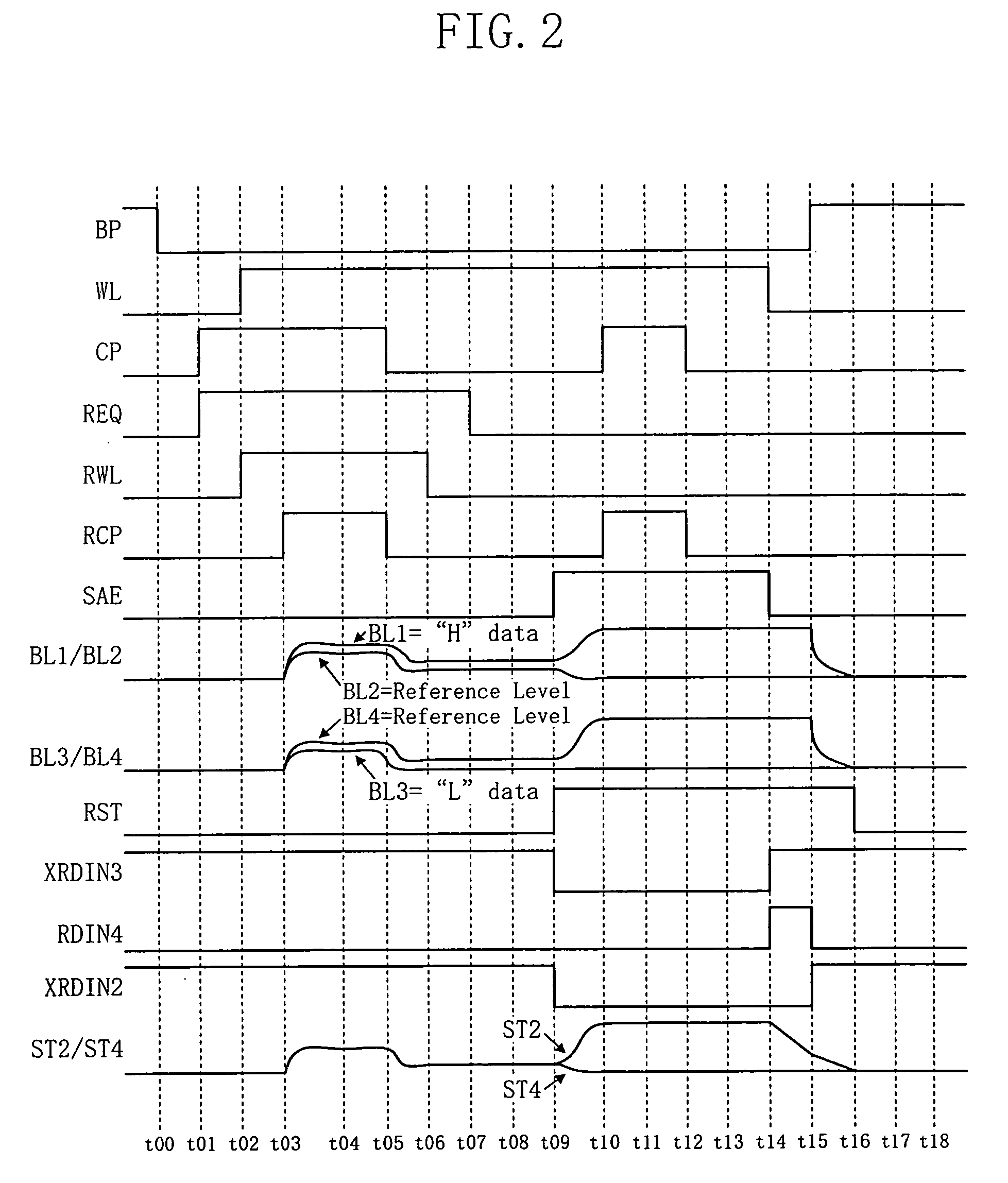
[0057] A ferroelectric memory of embodiment 1 of the present invention is described with reference to FIGS. 1 and 2.

[0058]FIG. 1 shows a circuit structure of a ferroelectric memory according to embodiments 1 and 2 of the present invention. FIG. 2 illustrates an operation timing of the ferroelectric memory according to embodiment 1.

[0059] As shown in FIG. 1, the ferroelectric memory of embodiment 1 includes a first normal cell 1 and a second normal cell 2 as memory cells for storing data. The first normal cell 1 is formed by a first transistor T1 and a first ferroelectric capacitor C1. The gate of the first transistor T1 is connected to a word line WL, and the drain of the first transistor T1 is connected to a first bit line BL1. The first electrode of the first ferroelectric capacitor C1 is connected to the source of the first transistor T1, and the second electrode of the first ferroelectric capacitor C1 is connected to a cell plate line CP. The second normal cell 2 is formed by ...

embodiment 2

[0088] Hereinafter, a ferroelectric memory of embodiment 2 of the present invention is described with reference to FIGS. 1 and 3.

[0089]FIG. 1 shows a circuit structure of a ferroelectric memory according to embodiments 1 and 2 of the present invention. FIG. 3 illustrates an operation timing of the ferroelectric memory according to embodiment 2. The descriptions of the circuit structure of FIG. 1 are the same as those provided in embodiment 1 and are therefore omitted herein.

[0090] Next, a circuit operation of the ferroelectric memory of embodiment 2 is described with reference to FIG. 3. Herein, it is assumed that data “1” is stored in the first normal cell 1, data “0” is stored in the second normal cell 2, data “1” is stored in the first reference cell 3, and data “0” is stored in the second reference cell 4. Data “1” means that the ferroelectric capacitor has a residual dielectric polarization such that the first electrode is positive. Data “0” means that the ferroelectric capac...

embodiment 3

[0106] Hereinafter, a ferroelectric memory of embodiment 3 of the present invention is described with reference to FIG. 4.

[0107]FIG. 4 shows a circuit structure of a ferroelectric memory according to embodiment 3 of the present invention. In FIG. 4, the same elements as those shown in FIG. 1 are denoted by the same reference numerals, and the descriptions thereof are herein omitted.

[0108] As shown in FIG. 4, in the ferroelectric memory of embodiment 3, the second electrode of the second ferroelectric capacitor C2 in the first reference cell 3 which holds data “1” is connected to a first reference cell plate line RCPH, and the second electrode of the fourth ferroelectric capacitor C4 in the second reference cell 4 which holds data “0” is connected to a second reference cell plate line RCPL.

[0109] In the above structure, only the second electrode of the ferroelectric capacitor which holds data “1” is connected to the first reference cell plate line RCPH, and only the second electro...


PUM


Abstract

A ferroelectric memory of the present invention comprises: a plurality of normal cells, each of which includes a first ferroelectric capacitor for holding data and a first transistor connected to a first electrode of the first ferroelectric capacitor; a first bit line connected to the first transistor; a first bit line precharge circuit which is a switch circuit provided between the first bit line and a ground; and a word line connected to a gate of the first transistor. The word line is deactivated to disconnect the first ferroelectric capacitor from the first bit line before the first bit line precharge circuit is driven to discharge a potential of the first bit line.

Description

CROSS-REFERENCE TO RELATED APPLICATION [0001] This application claims priority under 35 U.S.C. § 119(a) on Japanese Patent Application No. 2004-151576 filed on May 21, 2004, the entire contents of the specification, drawings and claims of which are hereby incorporated by reference. BACKGROUND OF THE INVENTION [0002] The present invention relates to a ferroelectric memory wherein a ferroelectric capacitor is used for a memory cell and to a method for reading data from the ferroelectric memory. [0003] In recent years, with the progress of process miniaturization and increase in capacity, a larger number of ferroelectric memories have employed a memory cell formed by one transistor and one ferroelectric capacitor, which has a reduced memory cell size, in substitution for an existing memory cell formed by two transistors and two ferroelectric capacitors. A ferroelectric memory employing the memory cell formed by one transistor and one ferroelectric capacitor requires a reference cell fo...

Claims


Application Information

Patent Timeline
IPC IPC(8): G11C11/22H01L27/10
CPCG11C11/22
Inventor YAMAOKA, KUNISATOHIRANO, HIROSHIGEGOHOU, YASUSHIIWANARI, SHUNICHIMURAKUKI, YASUOSAKAGAMI, MASAHIKONAKAKUMA, TETSUJIMIKI, TAKASHI
Owner PANASONIC CORP
Learn More