Wireless node location mechanism featuring definition of search region to optimize location computation

a wireless node and search region technology, applied in the direction of navigation instruments, transmission monitoring, instruments, etc., can solve the problems of affecting the accuracy of the weakening of the magnitude or power of the radio signal as it travels from its source, and the difficulty of computing the location in the radio map of the radar system which best fits the signal strength

Active Publication Date: 2005-11-24
CISCO TECH INC
View PDF99 Cites 143 Cited by
  • Summary
  • Abstract
  • Description
  • Claims
  • Application Information

AI Technical Summary

Benefits of technology

[0019] The present invention provides methods, apparatuses and systems directed to a wireless node location mechanism that defines a search region to optimize the computations associated with estimating the location of a given wireless node. According to an implementation of the present invention, a coverage map associated with each radio receiver that records signal strength data is defined out to a threshold signal strength level. Before computing the estimated location of a given wireless nodes, a search region is defined based on the intersection of the coverage maps associated with each radio receiver whose signal strength measurements are used to estimate the location the wireless node. Some implementations of the present invention use information provided by the fact that certain radio receivers did not detect the wireless node to further optimize the location estimate. By defining a search region, which is a generally small area relative to the space encompassed by the entire RF environment, the present invention provides several advantages, such as reducing the processing time and / or power to compute estimated locations for wireless nodes. In one implementation, the present invention can be used to reduce the computation associated with finding the best matching location to a fixed cost regardless of the size of the wireless network environment and / or the number of radio transceivers. As discussed in more detail below, the wireless node location mechanism can be incorporated into wireless network environments, such as 802.11 networks, to estimate the location of mobile stations, rogue access points and other wireless nodes.

Problems solved by technology

Generally speaking, the magnitude or power of a radio signal weakens as it travels from its source.
However, the multipath phenomenon encountered in indoor RF environments, which include walls, windows, and other RF obstructions, does present certain difficulties for location systems using triangulation, since reflection and absorption of RF signals affects the correlation between signal strength and proximity.
Computing the location in the Radio Map of the RADAR system which best fits the signal strength observed by the mobile station can be quite computationally intensive, especially as the boundaries of the RF environment and / or the granularity of the location coordinates in the Radio Map increase.
While this circumstance does not represent a substantial limitation for the RADAR system, which involved a limited number of access points and location bins, this un-optimized search algorithm does not scale to large wireless network deployments, which may include hundreds to thousands of access points and hundreds of location bins in the coverage maps for each access point.
Moreover, the size of the database required to support wireless node location, according to the RADAR system, can become quite large.
Accordingly, this un-optimized search algorithm can place a significant burden on the processing resources associated with a wireless node location system, especially infrastructure-based systems that perform other functions, such as providing wireless network access to the mobile stations.

Method used


Image

  • Wireless node location mechanism featuring definition of search region to optimize location computation
  • Wireless node location mechanism featuring definition of search region to optimize location computation
  • Wireless node location mechanism featuring definition of search region to optimize location computation

Examples


Embodiment Construction

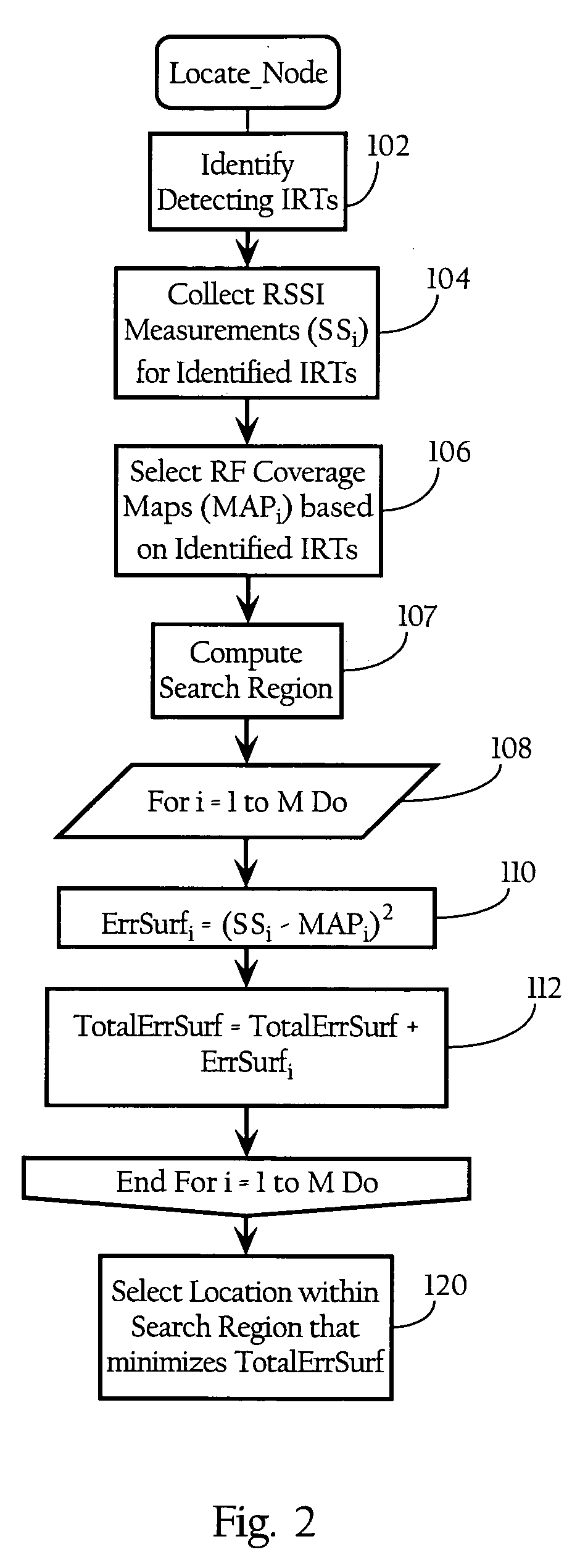
A. Wireless Node Location and Signal Strength Weighting Metric

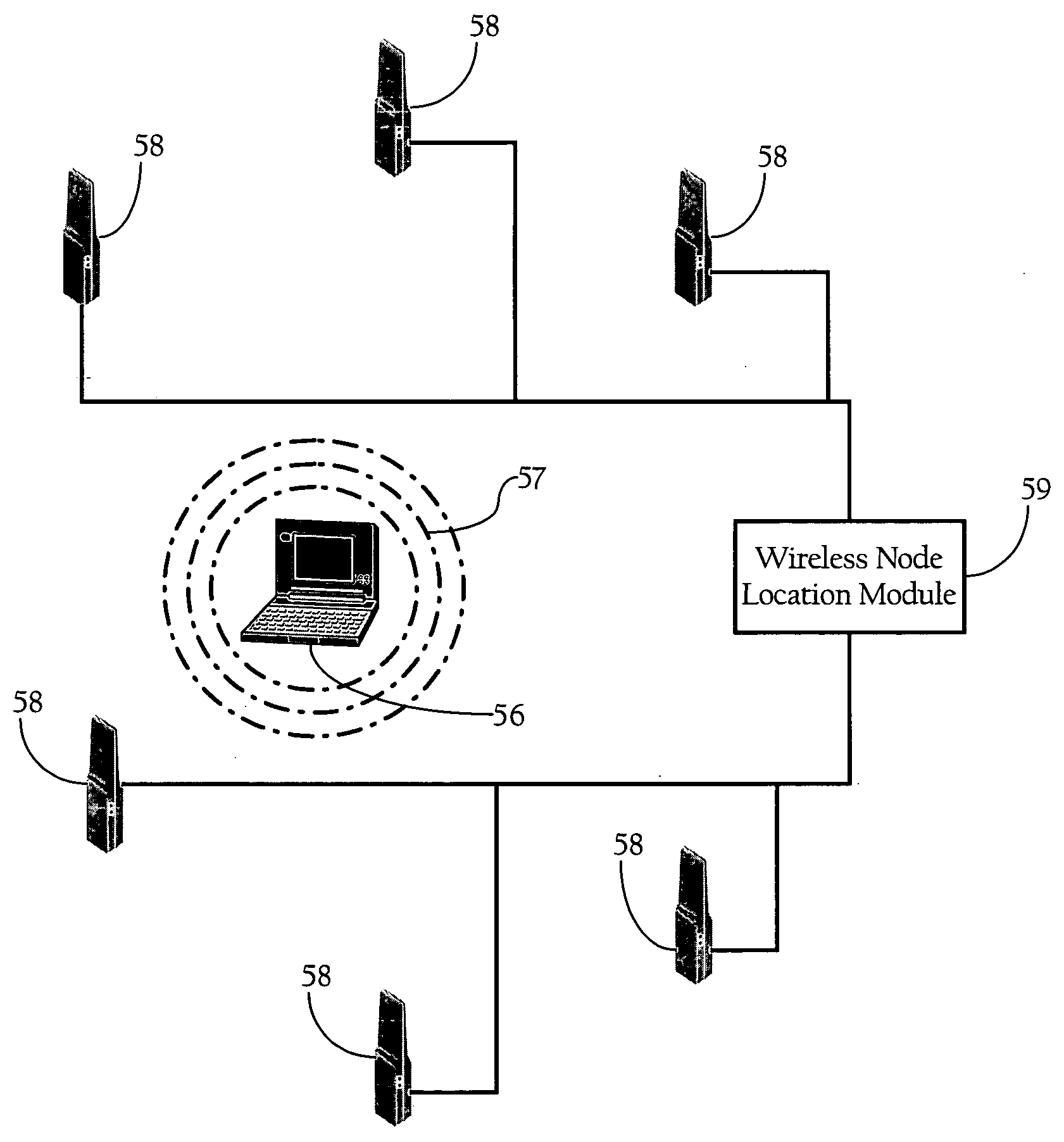
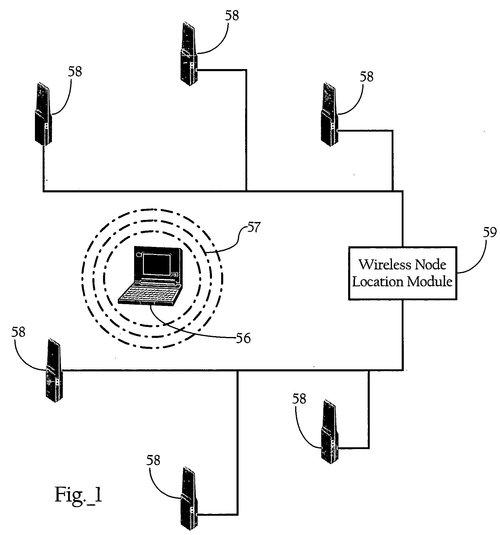
[0028]FIG. 1 illustrates the basic operating components of a wireless node location mechanism according to an implementation of the present invention. As FIG. 1 shows, the wireless node location mechanism includes a wireless node location module 59 and a plurality of infrastructure radio transceivers 58 disposed throughout a physical space. One skilled in the art will recognize that the system depicted in FIG. 1 represents an example of the basic components of the invention and is mostly for didactic purposes. Implementations of the present invention can involve hundreds to thousands of infrastructure radio transceivers 58 deployed over large geographic areas. As discussed more fully below, the functionality generally denoted by infrastructure radio transceivers 58 and wireless node location module 59 can be integrated into a variety of systems, such as wireless systems dedicated for location of wireless nodes, or WLAN or...


PUM


Abstract

A wireless node location mechanism that defines a search region to optimize the computations associated with estimating the location of a given wireless node. According to one implementation, a coverage map associated with each radio receiver that records signal strength data is defined out to a threshold signal strength level. Before computing the estimated location of a given wireless nodes, a search region is defined based on the intersection of the coverage maps associated with each radio receiver that detects the wireless node. Some implementations use information provided by the fact that certain radio receivers did not detect the wireless node to further optimize the location estimate. By defining a search region, which is a generally small area relative to the space encompassed by an entire RF environment, the present invention provides several advantages, such as reducing the processing time and / or power to compute estimated locations for wireless nodes.

Description

CROSS-REFERENCE TO RELATED PATENT APPLICATIONS [0001] This application makes reference to the following commonly owned U.S. patent applications and / or patents, which are incorporated herein by reference in their entirety for all purposes: [0002] U.S. patent application Ser. No. 10 / 155,938 in the name of Patrice R. Calhoun, Robert B. O'Hara, Jr. and Robert J. Friday, entitled “Method and System for Hierarchical Processing of Protocol Information in a Wireless LAN;”[0003] U.S. application Ser. No. 10 / 183,704 in the name of Robert J. Friday, Patrice R. Calhoun, Robert B. O'Hara, Jr., Alexander H. Hills and Paul F. Dietrich, and entitled “Method and System for Dynamically Assigning Channels Across Multiple Radios in a Wireless LAN;”[0004] U.S. patent application Ser. No. 10 / 407,357 in the name of Patrice R. Calhoun, Robert B. O'Hara, Jr. and Robert J. Friday, entitled “Method and System for Hierarchical Processing of Protocol Information in a Wireless LAN;”[0005] U.S. patent application...

Claims


Application Information

Patent Timeline
Patent Type & Authority Applications(United States)
IPC IPC(8): H04W24/00G01S19/06H04W64/00
CPCG01S5/02H04W64/00H04W24/00G01S5/0252G01S5/0244G01S5/02521
Inventor DIETRICH, PAUL F.DAVI, GREGG SCOTTFRIDAY, ROBERT J.
Owner CISCO TECH INC
Why Eureka
Try Eureka