Lateral needle injection apparatus and method

a technology of lateral needle and needle, which is applied in the field of delivery and injecting fluid into heart tissue, can solve the problems of increasing muscle enlargement, fluid may continue to leak over several seconds, and fluid may leak more pronouncedly with each muscle, so as to reduce the amount of fluid from the injection site

Inactive Publication Date: 2005-11-24
BOSTON SCI SCIMED INC
View PDF39 Cites 21 Cited by
  • Summary
  • Abstract
  • Description
  • Claims
  • Application Information

AI Technical Summary

Benefits of technology

[0015] As mentioned above, the primary penetrating member penetrates the heart tissue at the injection site in a different direction than the secondary penetrating member such that fluid leakage from the injection site is reduced. The primary penetrating member may penetrate the heart tissue generally orthogonal to the tissue surface at the injection site. The secondary penetrating member may penetrate the heart tissue in a direction that is generally lateral to the direction of the primary penetrating member. Preferably, the secondary penetrating member penetrates the heart tissue in a direction that is at an angle of about 5 to about 90 degrees relative to the direction of the primary penetrating member.

Problems solved by technology

A limitation to this method of delivering therapeutic agents to the heart is that the injected fluid tends to leak and / or disperse from the site of the injection after the needle is disengaged from the heart.
In fact, fluid may continue to leak over several seconds.
In the case of dynamic organs such as the heart, there may be more pronounced leakage with each muscle contraction.
However, it is common for the blood vessels to become occluded (blocked) or stenotic (narrowed).
The torturous path and small diameter of these blood vessels limit access to the stenotic lesions.
The sheer number and small size of these stenotic lesions make techniques such as cardiovascular by-pass surgery, angioplasty, and atherectomy impractical.
A limitation of this procedure is that the therapeutic agent may be quickly carried away by the flow of blood through the heart.

Method used


Image

  • Lateral needle injection apparatus and method
  • Lateral needle injection apparatus and method
  • Lateral needle injection apparatus and method

Examples


Embodiment Construction

[0027] The following detailed description should be read with reference to the drawings in which similar elements in different drawings are numbered the same. The drawings, which are not necessarily to scale, depict illustrative embodiments and are not intended to limit the scope of the invention.

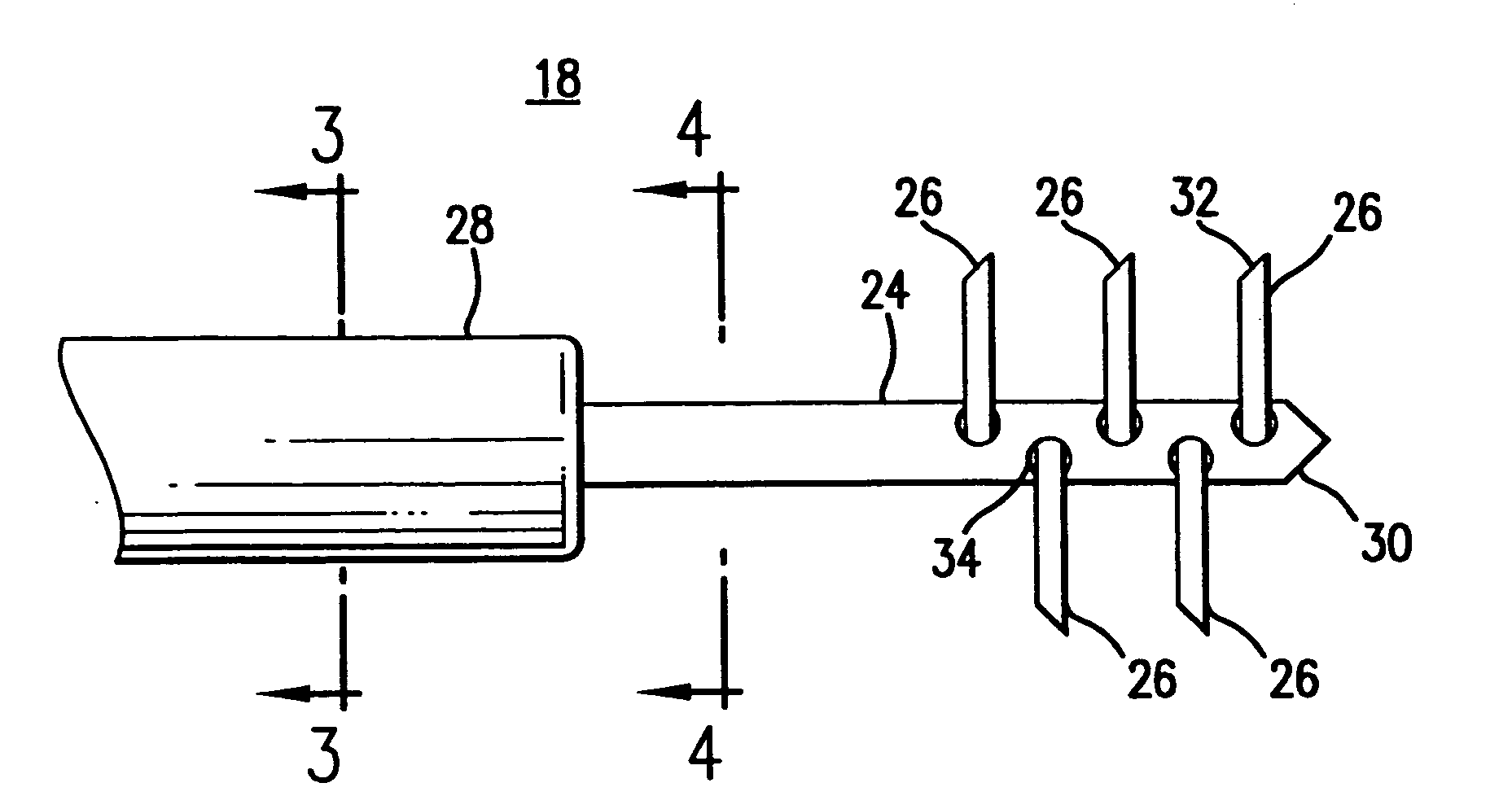
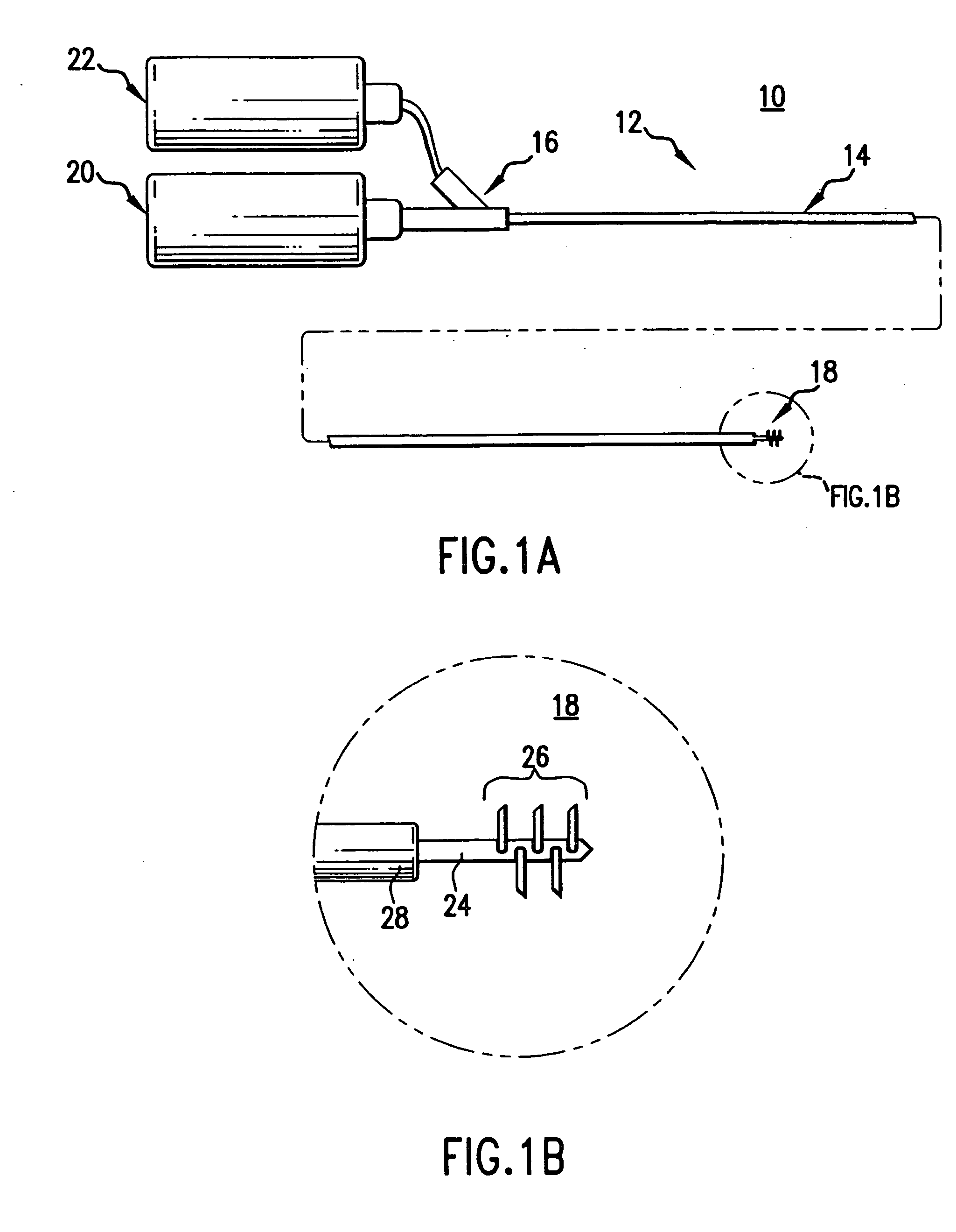
[0028] Refer now to FIG. 1A which illustrates a plan view of a catheter system 10 in accordance with an exemplary embodiment of the present invention. Catheter system 10 includes a catheter 12 having an elongate shaft 14. A manifold 16 is connected to the proximal end of the elongate shaft 14. The elongate shaft 14 includes a distal portion 18 which is illustrated in greater detail in FIG. 1B.

[0029] A pressurized fluid source 20 is connected to the catheter 12 by way of the manifold 16. Optionally, a vacuum source may be coupled to the side arm of the manifold 16. The pressurized fluid source 20 may comprise a conventional syringe or an automated pressure source such as a high pressure in...


PUM


Abstract

A device and method for delivering and injecting fluid into heart tissue utilizing a laterally directed needle to increase injectate (fluid) retention in the heart tissue. The device may comprise a catheter having a shaft wherein the distal end of the shaft includes a primary penetrating member and a secondary penetrating member. The secondary penetrating member includes an injection lumen in fluid communication with a pressurized fluid source. The primary penetrating member penetrates the heart tissue at the injection site in a first direction, and the secondary penetrating member penetrates the heart tissue in a second direction different from the first direction such that fluid leakage from the injection site is reduced and the volume of treated tissue is increased.

Description

RELATED APPLICATIONS [0001] This application claims the benefit of Provisional Patent Application Ser. No. 60 / 133,122, filed May 7, 1999, entitled INCREASED EFFICIENCY DIRECT INJECTION OF THERAPEUTIC AGENTS, which is hereby incorporated by reference. [0002] This application is related to co-pending patent application Ser. No. ______, filed on even date herewith, entitled INJECTION ARRAY APPARATUS AND METHOD; co-pending patent application Ser. No. ______, filed on even date herewith, entitled LATERAL NEEDLE-LESS INJECTION APPARATUS AND METHOD; and co-pending patent application Ser. No. ______, filed on even date herewith, entitled NEEDLE-LESS INJECTION APPARATUS AND METHOD.FIELD OF THE INVENTION [0003] The present invention generally relates to delivering and injecting fluid into heart tissue. More specifically, the present invention relates to delivering and injecting fluid into heart tissue utilizing a laterally directed needle. BACKGROUND OF THE INVENTION [0004] Injection catheter...

Claims


Application Information

Patent Timeline
Patent Type & Authority Applications(United States)
IPC IPC(8): A61B17/00A61B17/22A61B18/14A61M25/00A61M31/00
CPCA61B17/3207A61M2025/0089A61B18/1477A61B18/1492A61B2017/00247A61B2017/22077A61B2018/00214A61B2018/00291A61B2018/00392A61B2018/00589A61B2018/1425A61B2218/002A61M25/0084A61M2025/0086A61M2025/0087A61B17/3478
Inventor PALASIS, MARIAROSENTHAL, ARTHUR
Owner BOSTON SCI SCIMED INC
Why Eureka
Try Eureka