
Hand power tool, in particular drill hammer and/or jackhammer

a power tool and jackhammer technology, which is applied in the direction of manufacturing tools, drilling machines, slip couplings, etc., can solve the problems of affecting the concentricity of the tool fastened in place, the play between the coupling sleeve and the rotary sleeve, and the comparatively high cost of two-part design

Inactive Publication Date: 2005-12-01
ROBERT BOSCH GMBH
View PDF16 Cites 11 Cited by
  • Summary
  • Abstract
  • Description
  • Claims
  • Application Information

AI Technical Summary

Benefits of technology

[0003] Accordingly, it is an object of the present invention to provide a hand power tool, in particular a drill hammer and / or a jack hammer, which eliminates the disadvantages of the prior art.
[0006] The rotary sleeve may be designed as a one-piece component, which compared to known hand power tools can also be made markedly shorter. The result is a more-economical version with only one component, instead of the known two-part design. Any play between two components thus is dispensed with. Because the rotary sleeve is in one piece, it offers more installation space in the region of the striking pin of the hammering mechanism. A favorable extruded striking pin, which is less expensive, can therefore be employed. Moreover, advantageous bracing and sealing of the striking pin of the hammering mechanism are possible. It is also advantageous that the idling control of the hand power tool can be implemented by means of a favorable, time-tested O-ring impact-absorbing device. Moreover, the possibility exists of using favorable sintered components or precision- stamped components with multiple functions as detent elements. Bundling functions and reducing the number of components make it possible overall to achieve a great saving in terms of expenses and installation space while attaining high quality.

Problems solved by technology

This two-part design is comparatively expensive, since both the rotary sleeve part and the coupling sleeve have to be ground on both the outside and the inside.
Since the tool receptacle must be accommodated near the striking pin of the hammering mechanism, and the smaller-diameter coupling sleeve, problems arise in terms of bracing, sealing and damping in the region of the striking pin of the hammering mechanism.
Moreover, the play that exists between the coupling sleeve and the rotary sleeve impairs the concentricity of a tool fastened in place when it is driven to rotate.

Method used


Image

  • Hand power tool, in particular drill hammer and/or jackhammer
  • Hand power tool, in particular drill hammer and/or jackhammer
  • Hand power tool, in particular drill hammer and/or jackhammer

Examples


Embodiment Construction

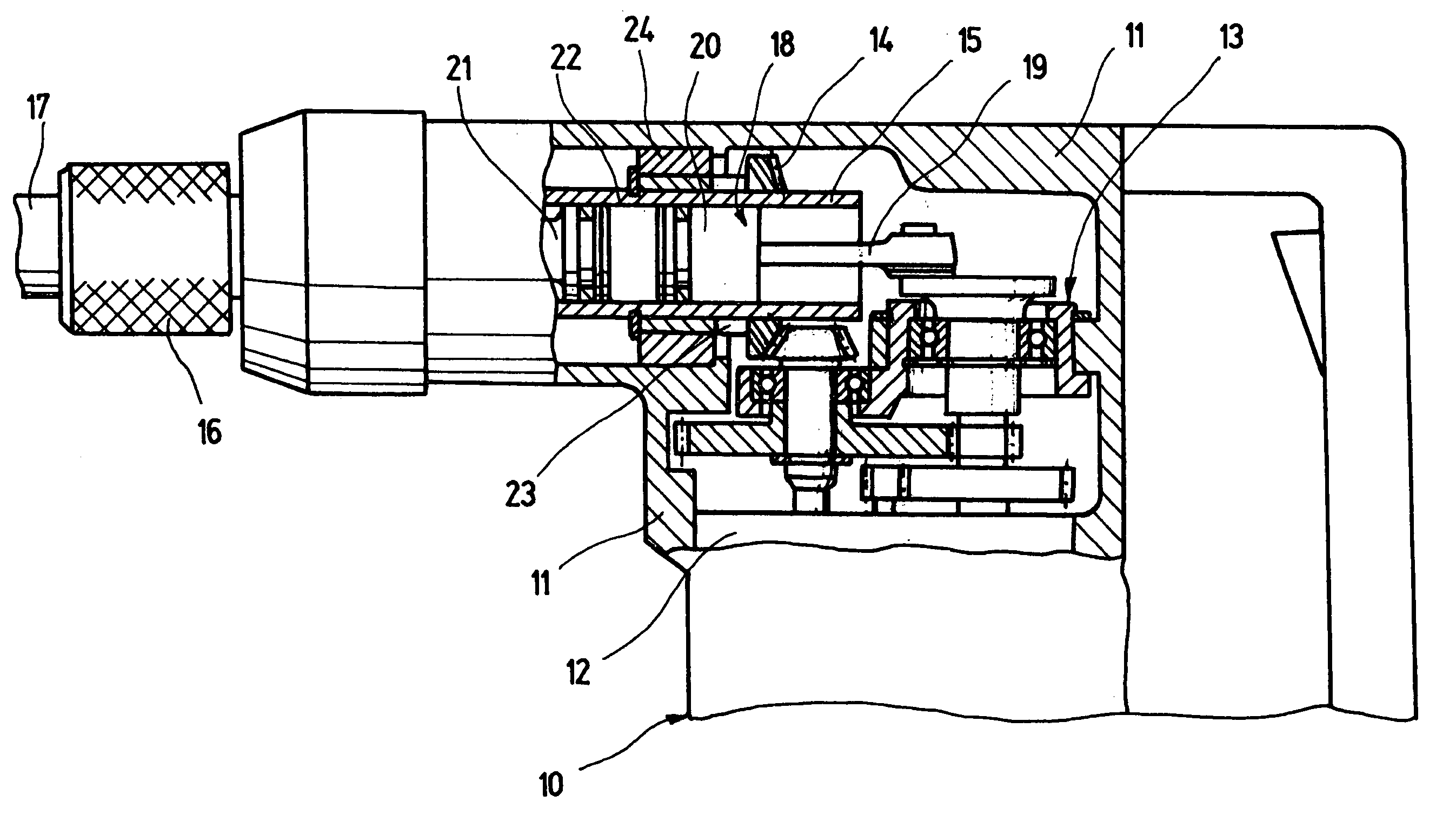
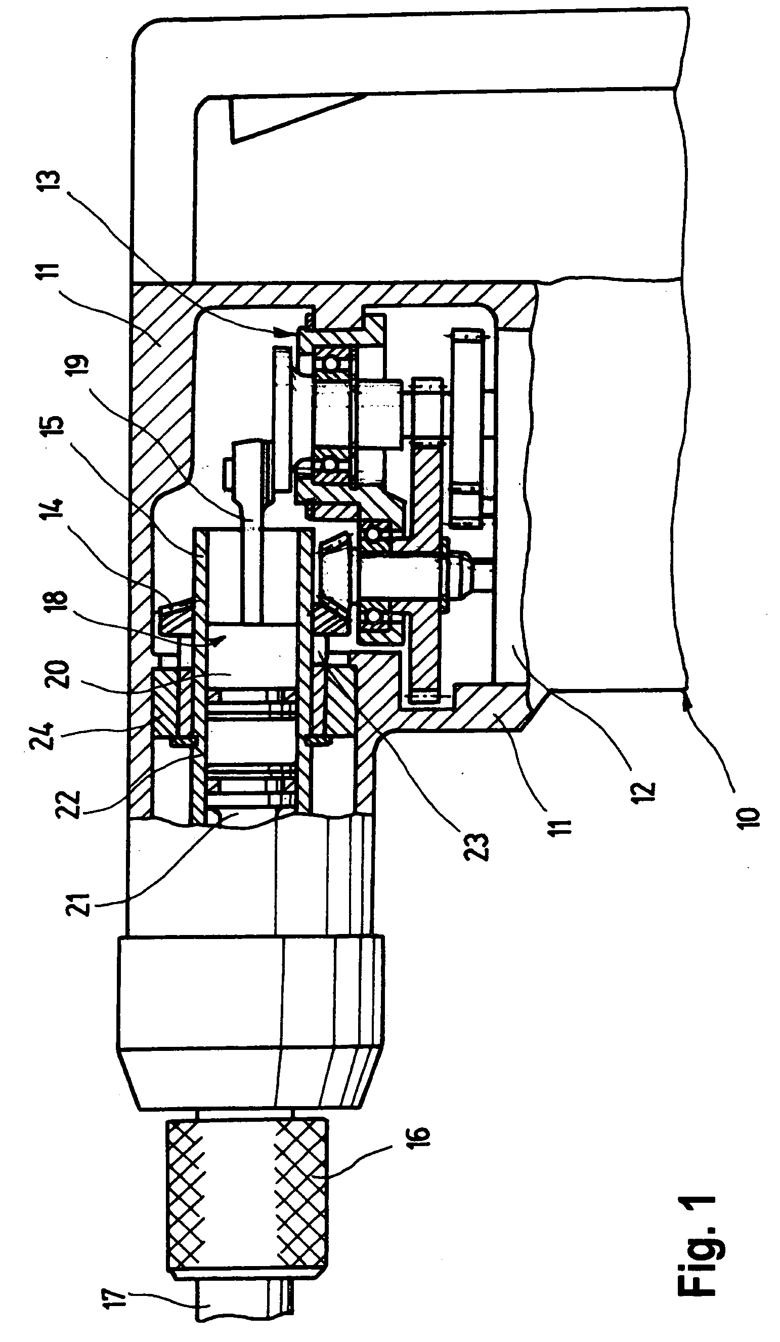
[0019] First, in conjunction with FIG. 1, the construction of a hand power tool 10, embodied in particular as a drill hammer and / or jackhammer, will be described briefly. The hand power tool 10 has a housing 11, which includes a drive motor 12, in particular electric, which works via a gear mechanism 13 on a drilling and / or hammering mechanism that follows it. To that end, the gear mechanism 13 is in engagement with a driving gear wheel 14, which is coupled for driving to a rotary sleeve 15. The driving gear wheel 14 preferably comprises a cone wheel. By means of the drive motor 12 and the gear mechanism 13, via the driving gear wheel 14, the rotary sleeve 15 and means of it a tool receptacle 16, in which a tool 17 can be guided, are drivable in rotation. Via the drive motor 12 and the gear mechanism 13, a hammering mechanism 18 can also be driven translationally by means of a preceding crank drive mechanism 19.

[0020] The hammering mechanism 18, inside the rotary sleeve 15, has a p...


PUM

PropertyMeasurementUnit
Forceaaaaaaaaaa
Displacementaaaaaaaaaa

Abstract

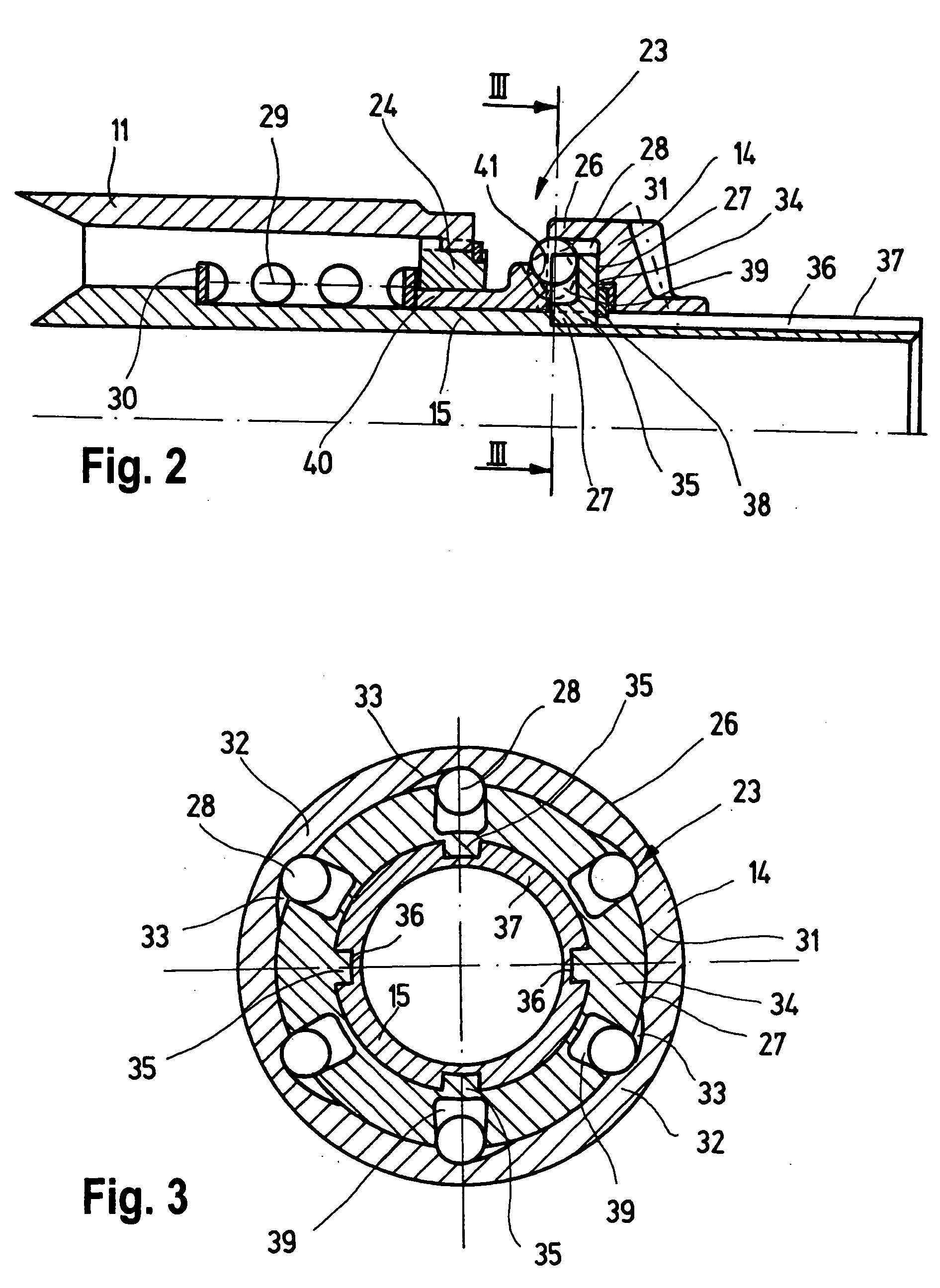
A hand power tool has a housing, and drive motor accommodated in the housing, a tool receptacle in which a tool is guided, a gear mechanism, a driving gear, and rotary sleeve arranged so that via the gear mechanism, the driving gear, and the rotary sleeve the tool receptacle is drivable in rotation, a crank drive mechanism and a hammering mechanism located inside the rotary sleeve so that the tool receptacle is drivable through the crank drive mechanism and the hammering mechanism translationally, and a safety coupling provided between the driving gear wheel and the rotary sleeve and formed so that the safety coupling separates if a limit torque is exceeded, the safety coupling being formed as an overlock coupling seated on the rotary sleeve and having two axially adjacent coupling parts that mesh in a form-locked manner by torque-transmitting transmission elements and are overlockable if the limit torque is exceeded counter to an axially acting elastic force, one of the coupling parts being a part associated with the driving gear wheel and rotatable relative to the rotary sleeve while the other of the coupling parts is coupled to the rotary sleeve in a way that transmits torque.

Description

BACKGROUND OF THE INVENTION [0001] The invention is based on a hand power tool, in particular a drill hammer and / or jackhammer. [0002] Known hand power tools of this kind are provided by the safety coupling, which is intended to protect the operator against an excessively great reaction torque if the tool being driven stops suddenly, for instance if a drilling tool seizes. In a known hand power tool, a safety coupling of this kind is provided in the region of the rotary sleeve, which is adjacent to the tool receptacle. The rotary sleeve is designed in two parts. On the end toward the drive mechanism, the sleeve part that receives the hammering mechanism receives a coupling sleeve inserted into it on the power takeoff end. The drive moment is transmitted by means of a plurality of transmission elements, in the form of balls, located in through bores of the rotary sleeve part. They are retained radially inward in approximately V-shaped ball pockets of the coupling sleeve and are retai...

Claims


Application Information

Patent Timeline
IPC IPC(8): B23B45/00B23B45/16B25D9/00B25D16/00B25F5/00F16D7/02F16D43/206
CPCB25D16/003B25D2211/003B25D2250/321B25D2250/225B25D2250/165B23B45/00B25D16/00F16D7/02F16D43/206
Inventor FRAUHAMMER, KARLSCHNERRING, HEINZBRAUN, WILLYKUHNLE, AXEL
Owner ROBERT BOSCH GMBH
Learn More