

Dual prism/filter for narrowband photometry
Inactive Publication Date: 2005-12-01
UNIV OF FLORIDA RES FOUNDATION INC
View PDF16 Cites 16 Cited by
- Summary
- Abstract
- Description
- Claims
- Application Information
AI Technical Summary
Benefits of technology
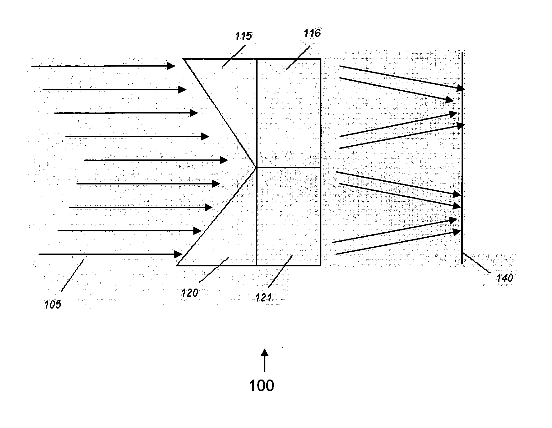
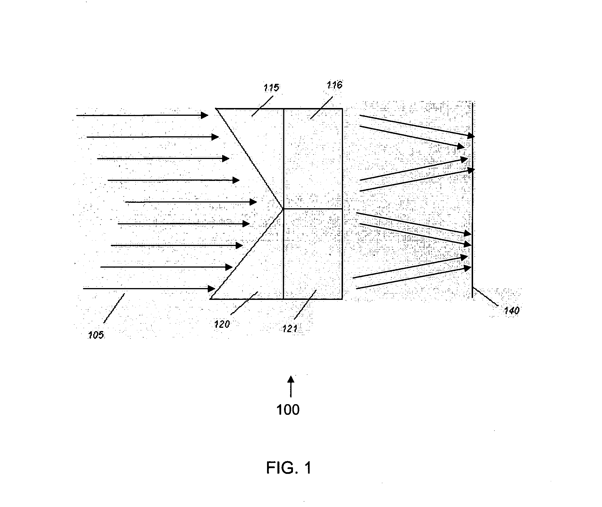
[0011] An optical bandpass separator for splitting target and continuum band signals includes a first optical path for selectively transmitting a target band signal. The first optical path includes a first prism and a first bandpass filter. The separator includes a second optical path non-overlapping with the first optical path for transmitting a continuum band signal. The second optical path includes a second prism and a second bandpass filter. A relatively small offset between the non-overlapping first and second optical paths allows the simultaneous and separate imaging or detection of the target band signal and the continuum band signal using a single imager or detector. As used herein, the term “light” generally refers to electromagnetic radiation including ultraviolet, visible and infrared radiation. However, the invention can be applied to shorter wavelength radiation such as x-rays, or longer wavelength radiation such as microwaves or radio waves.
[0014] A method of splitting target and continuum band signals includes the steps of receiving a light beam comprising a target band signal, simultaneously splitting the light beam into the target band signal and a continuum band signal, and detecting the target band signal and the continuum band signal on a single imager or single detector. By using the bandpass separator according to the present invention, such as at the input focal plane of an imaging system, the invention provides two physically-adjacent simultaneous images of the same field, one in each of the target and an adjacent portion of the continuum band. Through subtraction of the continuum band data from the target data, noise introduced by time variation in the atmospheric transmission and / or background can be eliminated.
Problems solved by technology
Such a sequential imaging approach, however, does not work well when the background emission and (especially) atmospheric transmission in these bands is significant relative to the target line, and is also highly time-variable.
This situation negatively impacts detection sensitivity, such as in the case of detection of landmines, as well as observations of scientifically significant features, including Paschen-α and Brackett-α features.
The cost of multiple camera systems is higher than the single camera systems because of reasons including the extra camera, lenses, and required synchronization electronics.
Method used
View moreImage
Smart ImageViewing Examples

Examples
examples
[0036] The present invention is further illustrated by the following specific examples, which should not be construed as limiting the scope or content of the invention in any way.
[0037]FIG. 3 shows an encircled energy diagram obtained from a Canarias InfraRed Camera Experiment (CIRCE) instrument including a Pa-α filter / prism device according an embodiment of the present invention. CIRCE is a near-infrared camera for the 10.4-meter Gran Telescopio Canarias (GTC) located in the Canary Islands, Spain. The data in FIG. 3 demonstrates that systems including filter / prism devices according to the invention provide good image quality in a typical astronomical infrared array camera.
Login to View More PUM
 Abstract
An optical bandpass separator and systems based thereon split target and continuum band signals. The separator includes a first optical path for selectively transmitting a target band signal. The first optical path includes a first prism and a first bandpass filter. The separator includes a second optical path non-overlapping with the first optical path for transmitting a continuum band signal. The second optical path includes a second prism and a second bandpass filter. The spacing of the first and second optical paths allows the simultaneous and separate imaging or detection of the target band signal and the continuum band signal using a single imager or detector.
Description
CROSS-REFERENCE TO RELATED APPLICATIONS [0001] Not applicable. STATEMENT REGARDING FEDERALLY SPONSORED RESEARCH OR DEVELOPMENT [0002] Not applicable. FIELD OF THE INVENTION [0003] This invention relates to detection and imaging systems, in particular, to narrowband detection and imaging systems which separate a target absorption or emission band from a continuum band using a single measurement. BACKGROUND OF THE INVENTION [0004] Infrared (“IR”) sensing arrays are widely used to capture images of objects that radiate in the infrared spectrum, generally defined as being in the wavelength range from about 750 nanometers to 1 millimeter. Each element of these sensing arrays use an infrared detector that reacts either to individual incident photons or to the total thermal energy caused by absorption of the incident photons to produce an electrical signal. The electrical signals produced by the sensing array are typically read out and processed to produce a digital electronic image indica...
Claims
Login to View More Application Information
Patent Timeline
 IPC IPC(8): G01J1/04G01J3/02G01J3/28G01J3/30G01J3/36
CPCG01J1/04G01J1/0477G01J1/0492G01J3/36G01J3/0205G01J3/30G01J3/02
InventorEIKENBERRY, STEPHEN SCOTT
OwnerUNIV OF FLORIDA RES FOUNDATION INC