Plasma display panel

a technology of display panel and plasma, which is applied in the direction of gas exhaustion means, solid cathodes, gas-filled discharge tubes, etc., can solve the problem of reducing the image display characteristics of pdp

Inactive Publication Date: 2005-12-01
SAMSUNG SDI CO LTD
View PDF11 Cites 5 Cited by
  • Summary
  • Abstract
  • Description
  • Claims
  • Application Information

AI Technical Summary

Benefits of technology

[0010] The present invention provides a plasma display panel (PDP) in which a high purity discharge gas can be filled by readily exhausting impurity gases generated when manufacturing the PDP while simultaneously filling a discharge gas into the discharge cells and maintaining the strength of barrier ribs at a predetermined level.
[0012] The structure of the PDP allows for a high purity discharge gas to be filled in the discharge cells while simultaneously exhausting the impurity gases generated during the process of manufacturing the PDP through an exhaust channel. A possible reduction in the strength of the barrier ribs due to the exhaust channel can be prevented by forming both side walls of the barrier ribs, which form the exhaust channel, in an arc-like shape.

Problems solved by technology

However, impurity gases often enter and remain in the PDP in the course of manufacturing the PDP, and the impurity gases mix with a discharge gas injected into the PDP without being discharged to the outside.
The contamination of the discharge gas can change the characteristics of discharge, and can eventually reduce the image display characteristics of the PDP.

Method used


Image

  • Plasma display panel
  • Plasma display panel
  • Plasma display panel

Examples


Embodiment Construction

[0022] The present invention will now be described more fully with reference to the accompanying drawings in which exemplary embodiments of the invention are shown.

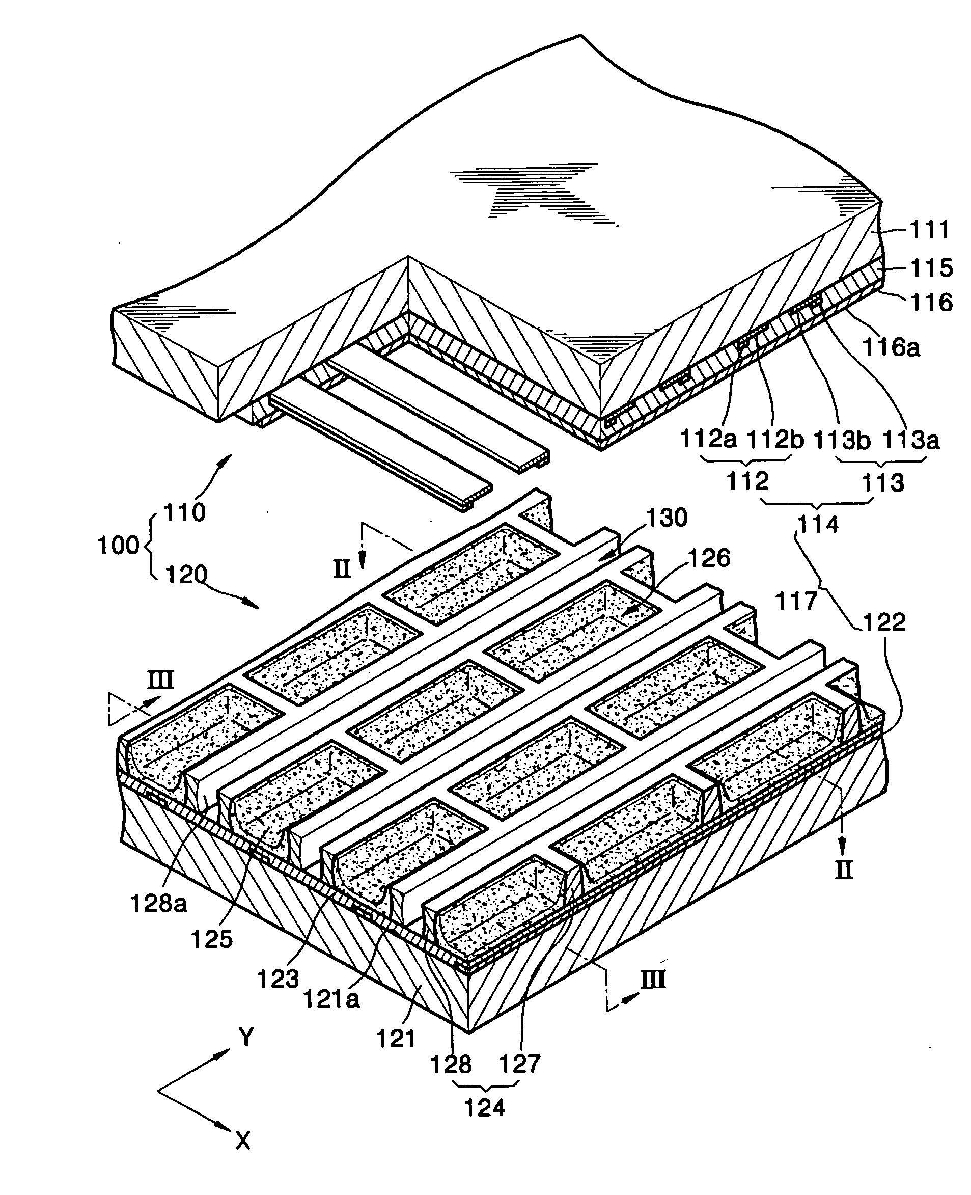
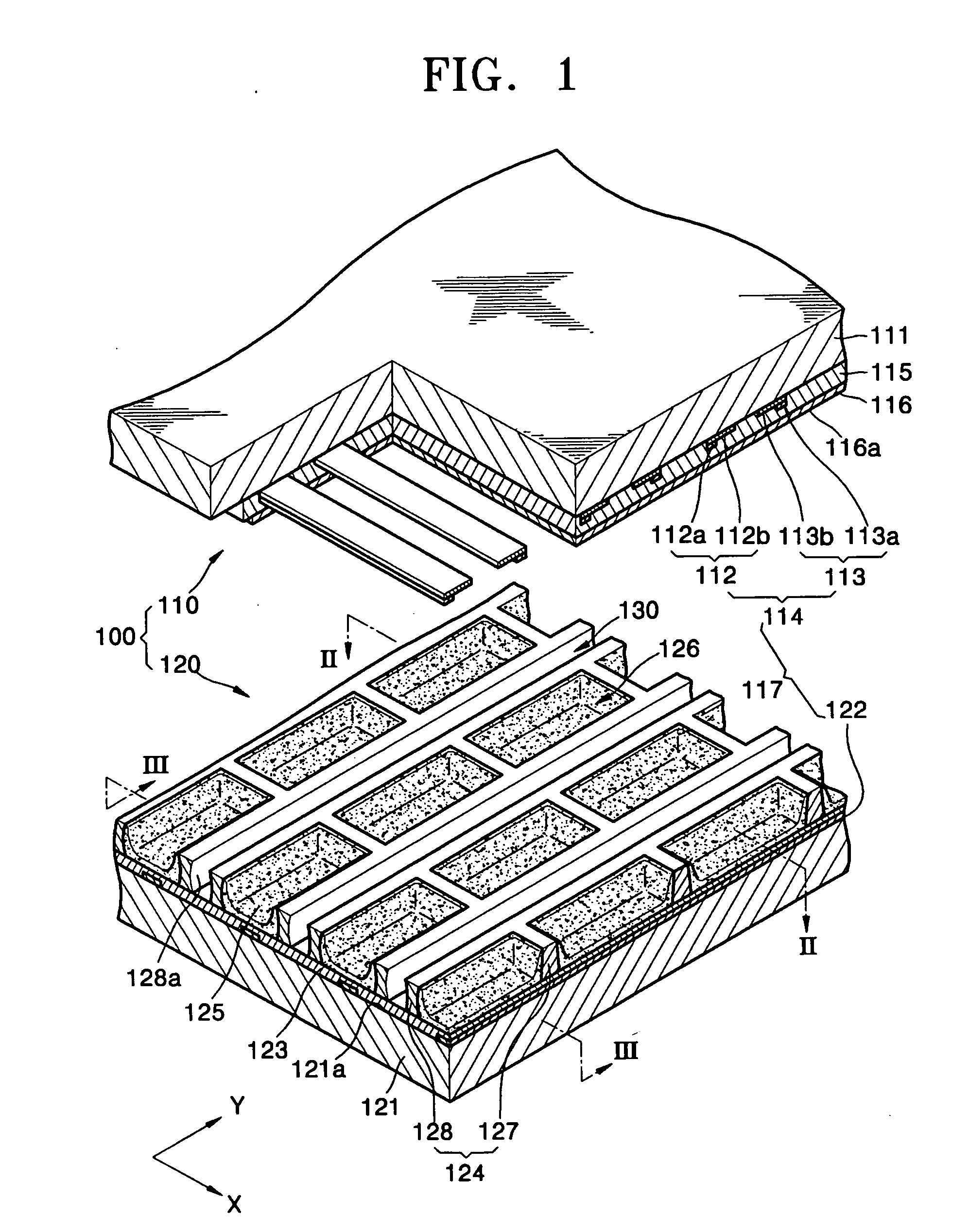
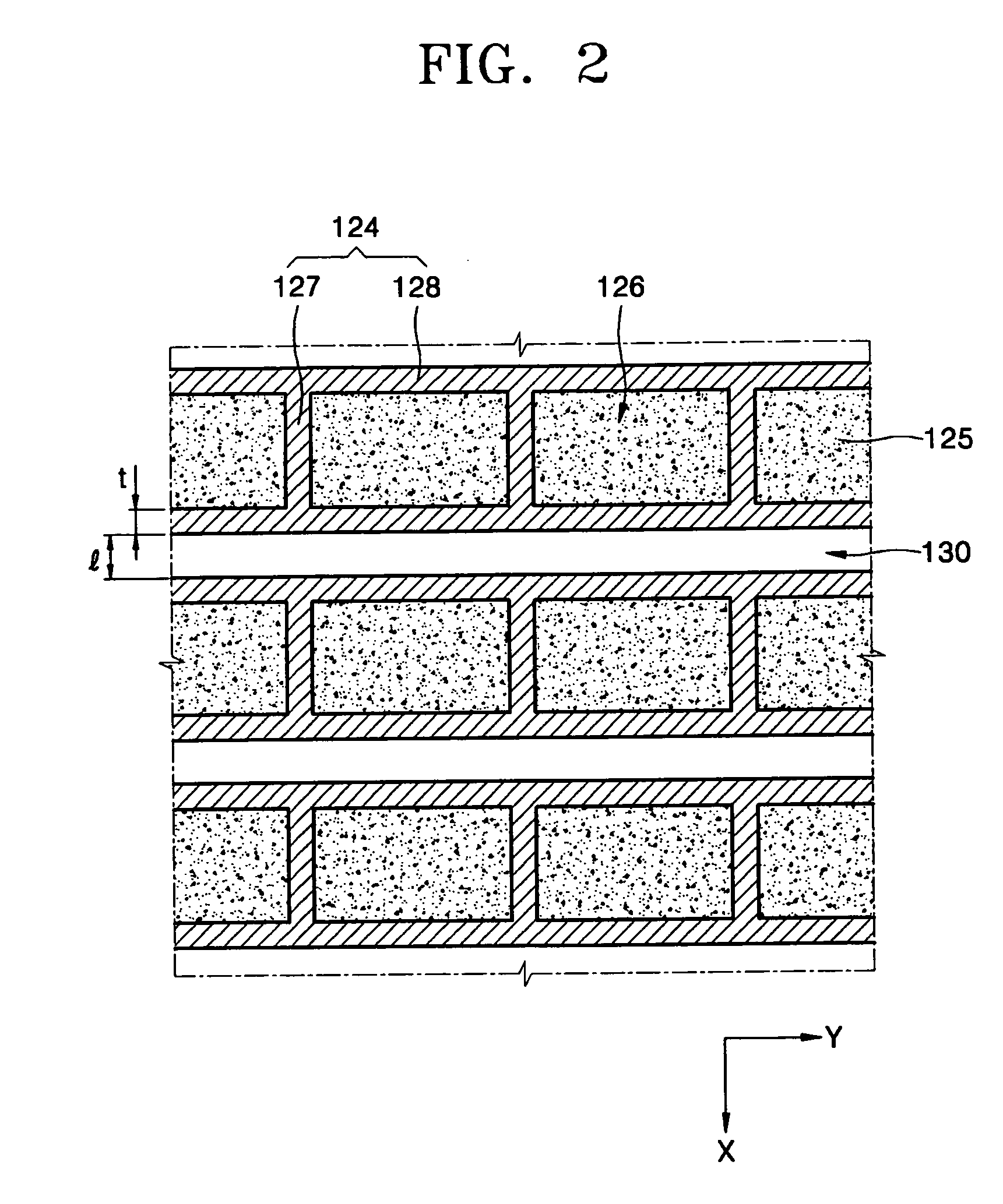
[0023]FIG. 1 is a broken perspective view of a PDP according to an embodiment of the present invention, while FIGS. 2 and 3 are cross-sectional views taken along lines II-II and III-III, respectively, of FIG. 1.

[0024] Referring to FIGS. 1 through 3, a PDP 100 comprises a front panel 110 and a rear panel 120. The front panel 110 includes a front substrate 111, a plurality of sustaining electrode pairs 114, each including an X electrode 113 and a Y electrode 112, which are parts of discharge electrodes 117 disposed on a rear surface of the front substrate 111, a front dielectric layer 115 that covers the sustaining electrode pairs 114, and a protective layer 116 that covers the front dielectric layer 115.

[0025] The accumulation of wall charge in the front dielectric layer 115 so as to generate a discharge on a rear surfa...


PUM


Abstract

A plasma display panel (PDP) is characterized such that the strength of barrier ribs can be maintained, impurity gases can be easily exhausted, and a discharge gas can be smoothly filled in the discharge cells when manufacturing the PDP. The PDP includes: a transparent front substrate; a rear substrate disposed facing the front substrate; a plurality of discharge electrodes disposed between the front substrate and the rear substrate; a plurality of barrier ribs disposed between the front substrate and the rear substrate, and defining a plurality of discharge cells which are spaces for generating a discharge, the barrier ribs having side walls that define an exhaust channel formed in at least a portion between the discharge cells, at least one of the side walls having an arc-like shape; a phosphor layer disposed in each of the discharge cells; and a discharge gas filled in the discharge cells.

Description

CLAIM OF PRIORITY [0001] This application makes reference to, incorporates the same herein, and claims all benefits accruing under 35 U.S.C. §119 from an application entitled PLASMA DISPLAY PANEL, earlier filed in the Korean Intellectual Property Office on 25 May 2004 and there duly assigned Serial No. 10-2004-0037352. BACKGROUND OF THE INVENTION [0002] 1. Technical Field [0003] The present invention relates to a plasma display panel (PDP) and, more specifically, to a PDP in which an impurity gas can be easily exhausted and a discharge gas can be smoothly filled in discharge cells when manufacturing the PDP while maintaining the strength of barrier ribs of the PDP. [0004] 2. Related Art [0005] Plasma display panels are display devices that display a predetermined image by exciting a phosphor material with ultra violet rays generated from a gas discharge, and they are expected to be the next generation of thin display devices since they can be manufactured with a large screen having ...

Claims


Application Information

Patent Timeline
IPC IPC(8): H01J9/39H01J9/395H01J17/49
CPCH01J9/39H01J9/395H01J2211/365H01J11/36H01J11/54H01J11/12H01J2211/361H01J2211/363
Inventor KANG, TAE-KYOUNGKIM, YONG-JUN
Owner SAMSUNG SDI CO LTD
Why Eureka
Try Eureka