
Exhaust gas purification system for internal combustion engine and exhaust gas purification method therefor

a technology of exhaust gas purification system and internal combustion engine, which is applied in the direction of engine components, machines/engines, mechanical apparatus, etc., can solve the problems of backpressure increase, and deterioration of fuel economy, so as to increase the amount of oxygen reacting with the pm, the effect of accurately calculating the regeneration speed of the filter

Inactive Publication Date: 2008-02-14
TOYOTA JIDOSHA KK
View PDF8 Cites 14 Cited by
  • Summary
  • Abstract
  • Description
  • Claims
  • Application Information

AI Technical Summary

Benefits of technology

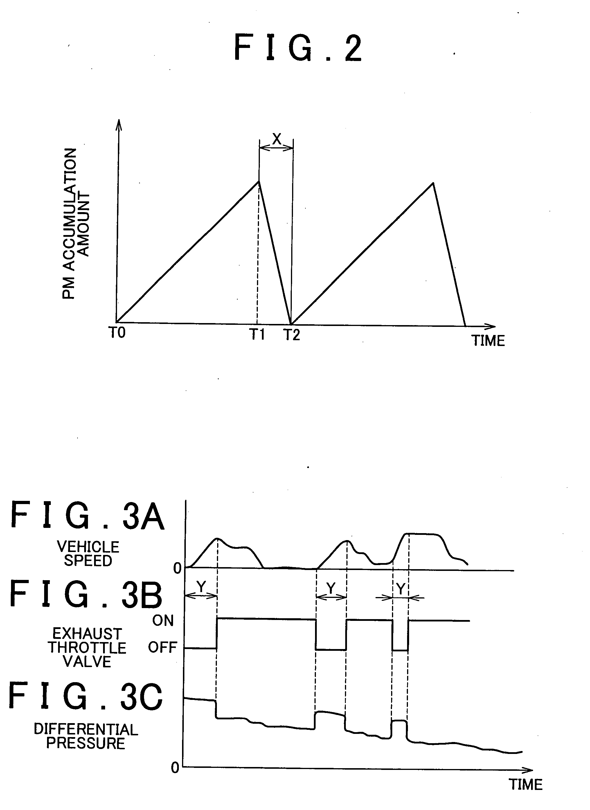
[0014] Therefore, using the condition that a value obtained through the division of the differential pressure by the volume of the exhaust gas decreases in accordance with the exhaust backpressure, the increase in the exhaust backpressure in the portion of the exhaust passage upstream of the exhaust throttle valve is calculated based upon values such as a change amount of the differential pressure, the volume of the exhaust gas and a temperature of the exhaust gas. Whether the exhaust throttle valve is malfunctioning is determined based upon the increase in the exhaust backpressure. That is, if the increase in the exhaust backpressure is less than an assumed increase when the exhaust throttle valve is operated, it is determined that the opening amount of the exhaust throttle valve has not been reduced to the desired opening amount. Thus, it is determined that the exhaust throttle valve is malfunctioning. Thereby, the temperature and the regeneration speed of the filter can increase sooner to their proper levels. The PM thus can be almost completely burned. Meanwhile, if the increase in the exhaust backpressure reaches the assumed increase when the exhaust throttle valve is operated, it is determined that the exhaust throttle valve is normal. The filter thus can be properly regenerated. As thus discussed, the increase in the exhaust backpressure can provide the accurate malfunction determination of the exhaust throttle valve even though the differential pressure and the change amount of the differential pressure vary due to the amount of accumulated PM.
[0018] According to the above construction, the regeneration degree of the filter is estimated based upon the differential pressure detected by the differential pressure sensor unless it is determined that the exhaust throttle valve is malfunctioning. If the amount of accumulated PM trapped by the filter is large, the differential pressure is greater because of the pressure loss caused by the PM, and the decrease in the differential pressure resulting from the operation of the exhaust throttle valve is greater. On the other hand, if the amount of accumulated PM is small, the differential pressure is smaller, and the decrease in the differential pressure resulting from the operation of the exhaust throttle valve is smaller. Therefore, the amount of accumulated PM trapped by the filter and the regeneration degree of the filter may be estimated based upon the differential pressure and the change in the differential pressure. Accordingly, the termination time of the regeneration of the filter may be properly determined, and the unnecessary or insufficient regeneration of the filter may be prevented. As thus described, a malfunction of the exhaust throttle valve is determined based upon the change in the differential pressure. Whenever the exhaust throttle valve operates normally, the regeneration degree of the filter can be estimated based upon the differential pressure.
[0020] According to the above construction, the increase in the exhaust backpressure in the portion of the exhaust passage upstream of the exhaust throttle valve is calculated based upon the change in the differential pressure detected by the differential pressure sensor, and the regeneration speed of the filter corresponding to the increase in the exhaust backpressure is calculated to estimate the regeneration degree. When the exhaust backpressure increases, the amount of oxygen reacting with the PM increases because of increase of the volume of the exhaust gas. The burning speed of the PM thus increases in proportion to the exhaust backpressure. Therefore, using the calculated increase in the exhaust backpressure, the regeneration speed of the filter may be accurately calculated. The regeneration degree of the filter is properly estimated, accordingly.

Problems solved by technology

In such an exhaust gas purification system, the exhaust backpressure increases as the amount of accumulated PM trapped by the filter increases and invites problems such as deterioration of fuel economy.
This situation can invite deterioration of fuel economy resulting from the increase of the exhaust backpressure and / or abnormal burning resulting from the trapping of excessive PM.
Meanwhile, the exhaust gas purification systems described above have the following drawbacks when the exhaust throttle valve malfunctions, because the systems control the exhaust temperature by controlling the opening amount of the exhaust throttle valve.
That is, if the opening amount of the exhaust throttle valve is not reduced to a desired opening amount under the filter regeneration condition, the exhaust temperature does not increase sufficiently and the oxidization of the PM trapped by the filter does not proceed adequately.
In this connection, the regeneration speed of the filter is estimated erroneously, and the filter regeneration may be stopped prematurely.
Thus, a significant portion of the accumulated PM remains trapped in the filter.
If the PM remains, the exhaust backpressure may increase and adversely affect fuel economy.
Also, if an excessive amount of PM is trapped, the filter may melt as a result of abnormal burning of the PM.

Method used


Image

  • Exhaust gas purification system for internal combustion engine and exhaust gas purification method therefor
  • Exhaust gas purification system for internal combustion engine and exhaust gas purification method therefor
  • Exhaust gas purification system for internal combustion engine and exhaust gas purification method therefor

Examples


Embodiment Construction

[0034] With reference to FIGS. 1 through 6, an embodiment of the present invention will be described below.

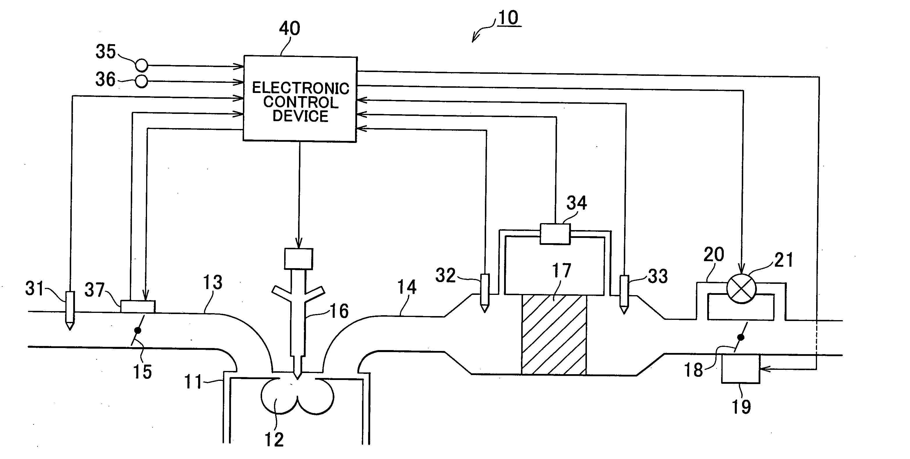
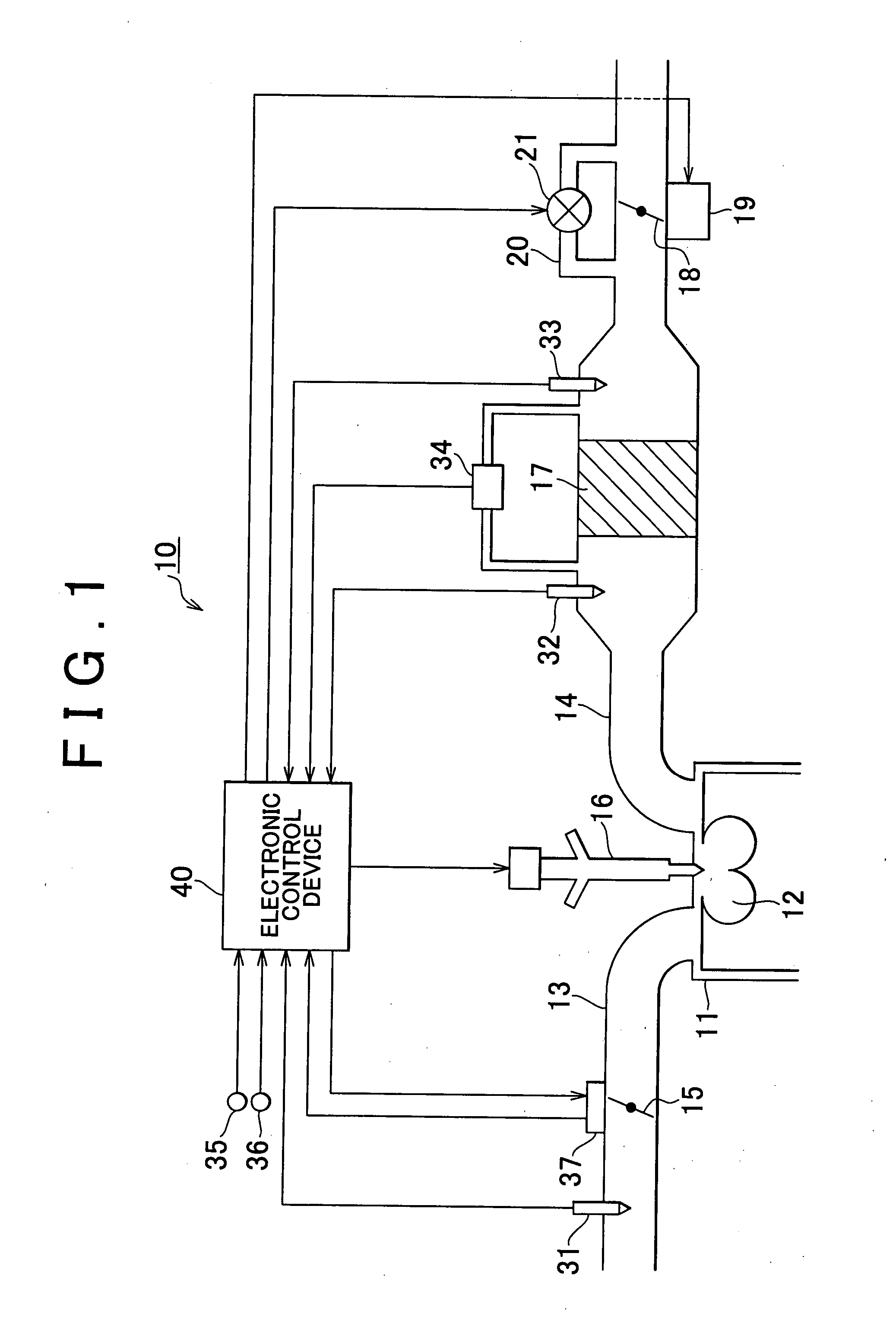
[0035]FIG. 1 is a block diagram of an internal combustion engine for an automobile, the engine having an exhaust gas purification system according to the invention. An engine 10 has a combustion chamber 12 defined in every cylinder 11, an intake passage 13 for delivering intake air to each combustion chamber 12, and an exhaust passage 14 through which exhaust gas formed by combustion in each combustion chamber 12 is discharged.

[0036] The intake passage 13 has an intake throttle valve 15 that can adjust the cross sectional area of the intake passage 13. The opening amount of the intake throttle valve 15 is adjusted to control an amount of air introduced into the combustion chamber 12. The air introduced in the combustion chamber 12 is mixed with fuel injected by a fuel injector 16 and directed toward the combustion chamber 12 to be a mixture. The mixture is burned in the combu...


PUM


Abstract

If an exhaust throttle valve changes to ON state from OFF state under a filter regeneration control condition for regenerating a PM filter, a differential pressure sensor detects a change of a differential pressure following an operation of the exhaust throttle valve. An increase in an exhaust backpressure is calculated based upon the change in the differential pressure. If the increase in the exhaust backpressure is lower than a predetermined value, the operation of the exhaust throttle valve is determined to be malfunctioning.

Description

INCORPORATION BY REFERENCE [0001] The disclosure of Japanese Patent Application No. 2006-182988 filed on Jul. 3, 2006, including the specification, drawings and abstract is incorporated herein by reference in its entirety. BACKGROUND OF THE INVENTION [0002] 1. Field of the Invention [0003] The invention relates to an exhaust gas purification system for an internal combustion engine that has a filter disposed in an exhaust passage for trapping particulate matter discharged from the engine and also relates to an exhaust gas purification method for such an internal combustion engine. [0004] 2. Description of the Related Art [0005] Conventionally, as an exhaust gas purification system applied to an internal combustion engine, such as a diesel engine for a vehicle, a system is known which includes a filter disposed in the exhaust passage for trapping particulate matter (PM) discharged from the engine. In such an exhaust gas purification system, the exhaust backpressure increases as the a...

Claims


Application Information

Patent Timeline
Patent Type & Authority Applications(United States)
IPC IPC(8): F01N3/023
CPCF01N3/023F01N3/0235F01N9/002Y02T10/47F01N2560/14F02D9/04F01N2560/08Y02T10/40
Inventor OTSUBO, YASUHIKOYOKOI, TATSUHISAMATSUNO, SHIGEHIROHODA, IKUO
Owner TOYOTA JIDOSHA KK
Learn More