

Control apparatus for internal combustion engine
A technology for internal combustion engines and control devices, applied in engine control, machine/engine, fuel injection control, etc., to achieve the effect of preventing melting
Inactive Publication Date: 2010-08-11
TOYOTA JIDOSHA KK
View PDF4 Cites 14 Cited by
- Summary
- Abstract
- Description
- Claims
- Application Information
AI Technical Summary
Problems solved by technology
Thus, the conventional system attempts to
Method used
View moreImage
Smart ImageViewing Examples

Examples
Example
[0030] First embodiment
Login to View More PUM
 Abstract
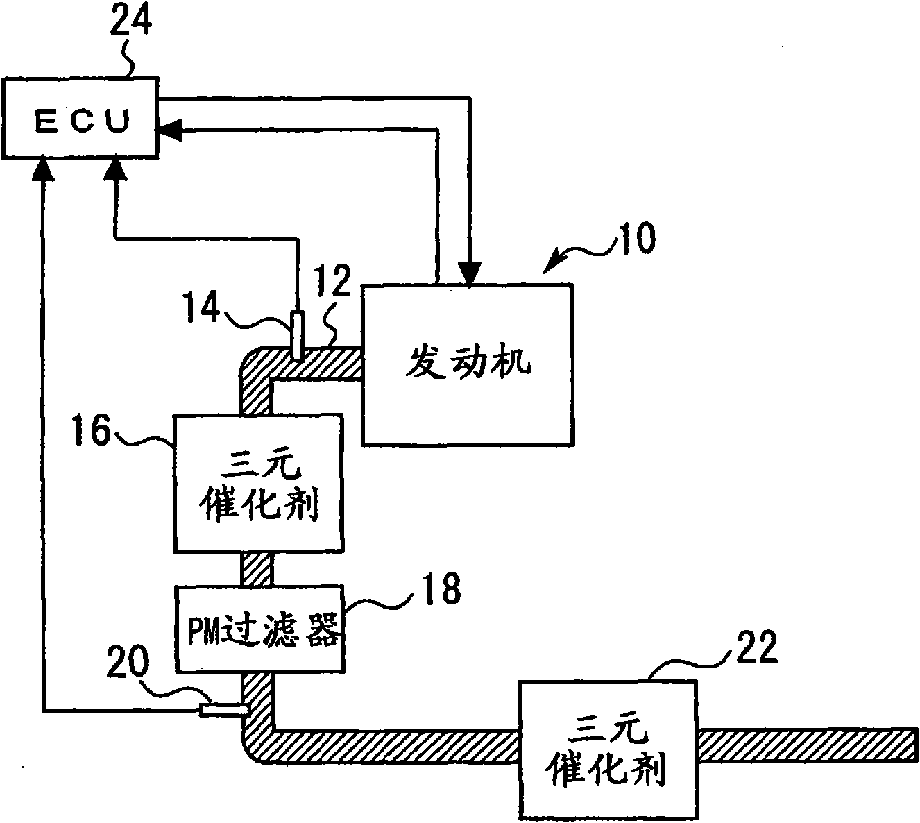
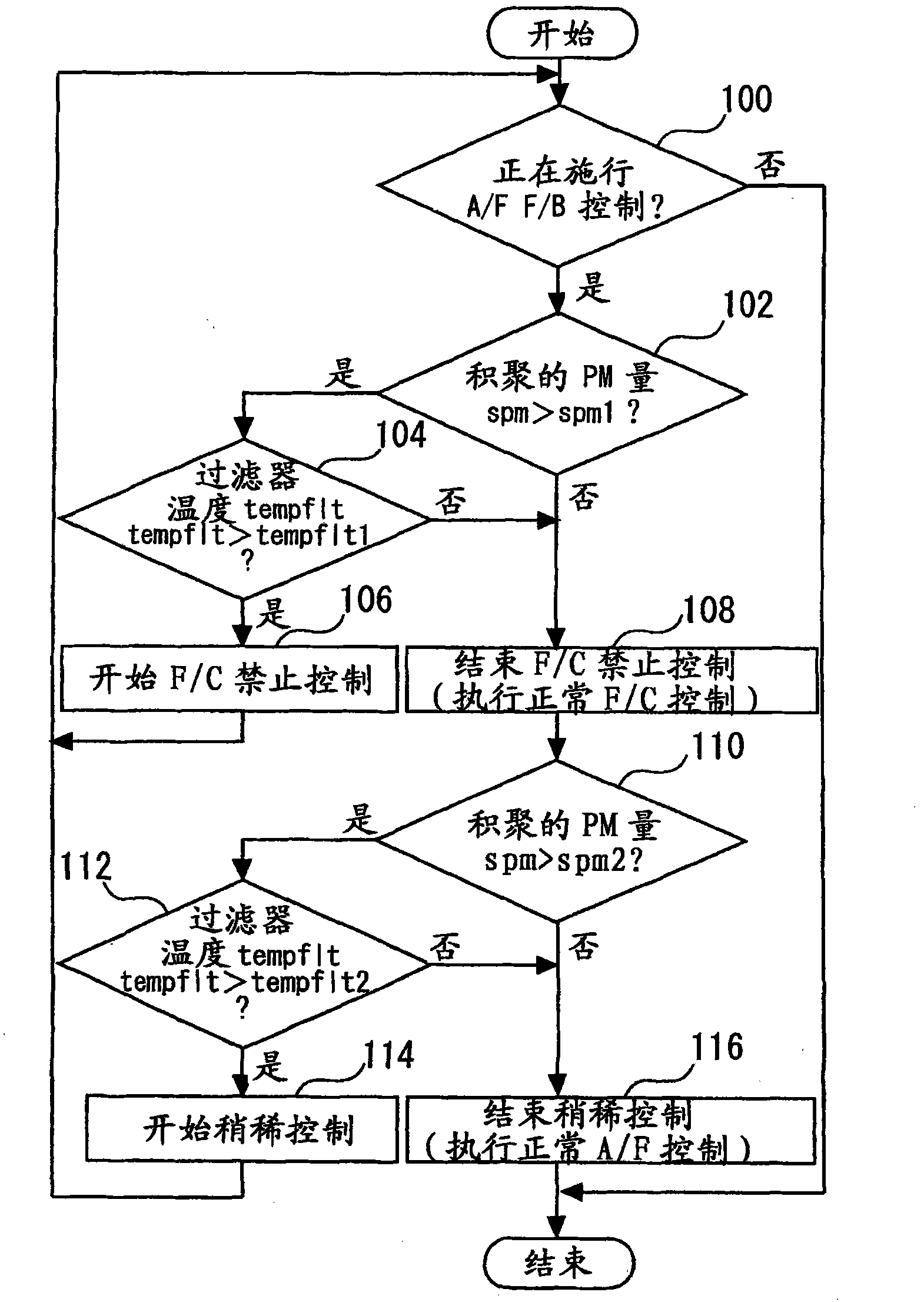
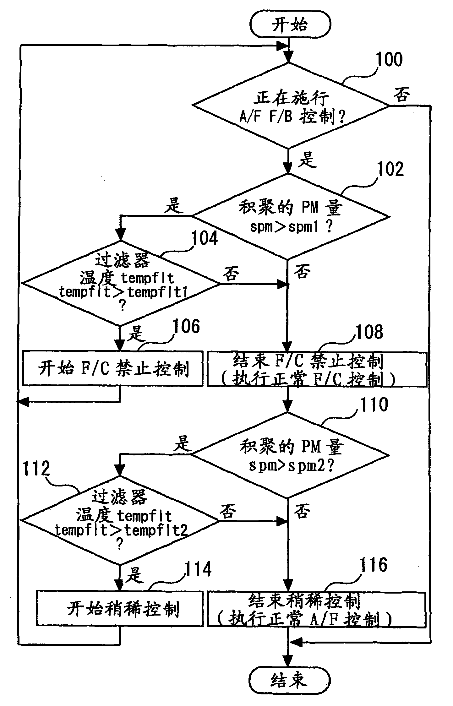
An internal combustion engine (10) is provided that performs stoichiometric burn operation under control for providing a stoichiometric air-fuel ratio as basic control for an air-fuel ratio. A particulate filter (PM filter) (18) is provided in an exhaust passage (12) of the engine (10) to trap particulate matter PM contained in exhaust gas. If it is judged that the PM filter (18) will have excessively elevated temperature, fuel cut is prohibited during deceleration. Otherwise, before the prohibition of the fuel cut, the air-fuel ratio of exhaust gas is controlled so that the atmosphere of the PM filter (18) is brought into an atmosphere slightly leaner than the stoichiometric air-fuel ratio.
Description
technical field [0001] The present invention relates generally to a control device for an internal combustion engine, and more particularly to a control device adapted to control an internal combustion engine equipped with a particulate filter for trapping particulate matter PM in the exhaust passage . Background technique [0002] For example, Patent Document 1 discloses an exhaust emission purification system for a diesel engine equipped with a particulate filter for trapping particulate matter PM (hereinafter referred to as "PM filter") in the exhaust passage. "). Such a conventional system is designed to decelerate only when it is determined that the PM filter will not have an excessively elevated temperature when the engine enters a deceleration state in which fuel supply is stopped (fuel cut) during regeneration of the PM filter. Smaller intake throttle opening angle and larger EGR valve opening angle. [0003] By performing the above-described control, the conventi...
Claims
Login to View More Application Information
Patent Timeline
 IPC IPC(8): F02D41/02F02D41/12F02D41/22
CPCF02D41/029F02D2200/0804F02D41/22F02D2200/0812F02D41/123
Inventor藤原孝彦小桥纪靖
OwnerTOYOTA JIDOSHA KK