
Engine system

An engine system and engine technology, applied in the directions of engine ignition, engine components, engine control, etc., can solve the problems of not considering pressure changes, difficult to accurately and well control the supply of air and hydrogen-rich gas mixture ratio, and achieve exhaust performance. and good fuel efficiency

Inactive Publication Date: 2008-09-03
HITACHI LTD
View PDF1 Cites 14 Cited by
  • Summary
  • Abstract
  • Description
  • Claims
  • Application Information

AI Technical Summary

Problems solved by technology

However, in the system described in Patent Document 1, since the pressure fluctuation of the hydrogen-rich gas supplied by the hydrogen supply device is not considered, it is difficult to accurately and well control the mixing ratio and supply amount of the air and the hydrogen-rich gas.

Method used


Image

  • Engine system
  • Engine system
  • Engine system

Examples


Embodiment Construction

[0025] Hereinafter, the embodiments of the present invention will be described with reference to the drawings.

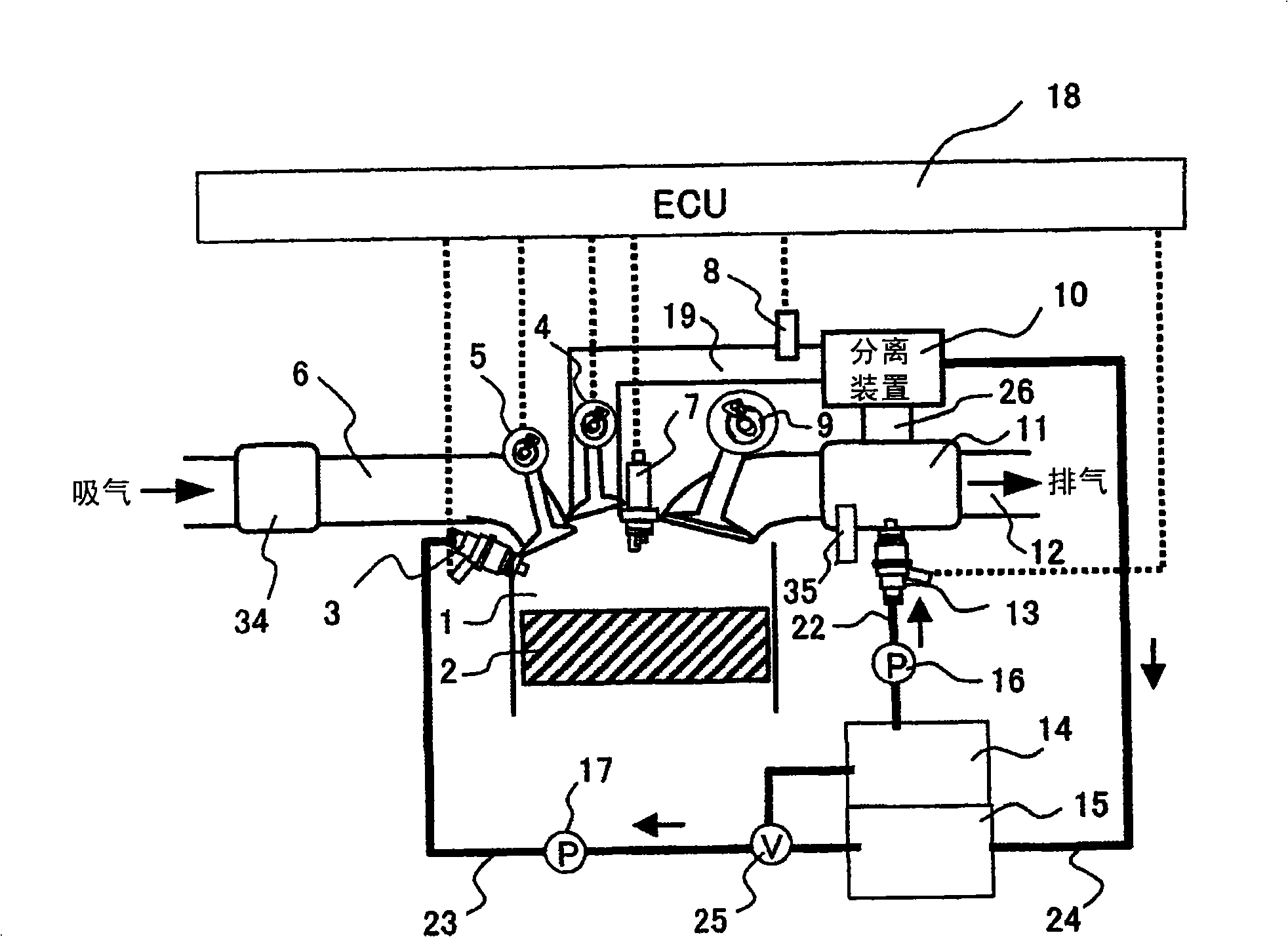
[0026] figure 1 It shows a system in which a hydrogen supply device 11 is installed on the exhaust pipe 12 of the engine for dehydrogenating a medium that chemically repeats storage and release of hydrogen, and the heat of the exhaust gas discharged from the engine 1 can be utilized. The hydrogenation medium is supplied to the hydrogen supply device 11 through the hydrogenation medium supply device 13. In addition, a catalyst temperature detection device 35 is installed on the hydrogen supply device 11.

[0027] The above medium means all substances that can chemically store and release hydrogen, such as gasoline, light oil, kerosene, heavy oil, decalin, cyclohexane, methylcyclohexane, naphthalene, benzene, toluene and other hydrocarbons Fuel and its mixed fuel, or hydrogen peroxide, ammonia, nitrogen, oxygen, etc. Among them, a medium that chemically stores hydrogen ...


PUM


Abstract

The invention provides an engine system using hydrogen as one of the fuels to drive the engine and control the supply quantity of the air and the hydrogen rich gas with good exhaust performance and fuel utilance. The engine system comprises a detection means for detecting the supply quantity or supply pressure of hydrogen rich gas which is disposed in a hydrogen rich gas supply pipe for supplying hydrogen rich gas to a combustion chamber of the engine, a hydrogen rich gas supply valve control means for controlling the supply of hydrogen rich gas by controlling the open / close timing and the amount of open / close lift of the hydrogen rich gas supply valve disposed in the combustion chamber of the engine based on the supply quantity or supply pressure detected by the detection means, an inlet valve for supplying air to the combustion chamber of the engine separately from the hydrogen rich gas supply valve, and an inlet valve control means for controlling the volume of air taken into the combustion chamber of the engine by the inlet valve.

Description

Technical field [0001] The invention relates to an engine system that uses hydrogen as one of the fuels to drive the engine. Background technique [0002] In the case of seeking to de-fossil fuel due to global warming issues, engine systems that use hydrogen as fuel to drive the engine are under development. As a method of supplying air and hydrogen into the cylinder (combustion chamber) of the engine, there are a method of supplying air and hydrogen to the cylinder from the same supply pipe and a method of supplying air and hydrogen to the cylinder from different supply pipes. Compared with the above-mentioned methods, in order to be able to supply a larger amount of mixed gas of air and hydrogen into the cylinder, it is preferable to adopt a method of separately supplying air and hydrogen to the cylinder from different supply pipes. Here, as a method of supplying hydrogen into the cylinder, there are a method of injecting hydrogen through an injector, and a method of supplying ...

Claims


Application Information

Patent Timeline
Patent Type & Authority Applications(China)
IPC IPC(8): F02M27/02F02B43/10F02D19/02F02M21/02
CPCF01N5/02F01N2610/04F02B23/104F02B43/04F02B2075/125F02D13/0226F02D13/0276F02D19/0628F02D19/081F02D41/0027F02D2041/147F02M25/12F02P5/1527F02D19/0644F02D19/0671F02D19/0692Y02T10/12Y02T10/30Y02T10/40
Inventor 岛田敦史石川敬郎小村昭义杉政昌俊板桥武之
Owner HITACHI LTD
Learn More